
Rubber crushing device for rubber production

A pulverizing device and rubber technology, applied in the rubber field, can solve the problems of affecting quality, pulverizing blade wear, blade gap, etc., to achieve the effect of improving the quality of plastics

Inactive Publication Date: 2020-08-04
周会文
View PDF13 Cites 1 Cited by
  • Summary
  • Abstract
  • Description
  • Claims
  • Application Information

AI Technical Summary

Problems solved by technology

[0003] The existing rubber crushing device directly washes and crushes the recovered rubber products, but for the plastic runway, impurities such as fine sand and gravel particles will still remain in the gaps between the rubber raised particles, and they will be directly thrown into the crushing In the warehouse, the rubber raw material will affect the overall quality due to the existence of impurities, and the fine sand and gravel particles will aggravate the wear of the crushing blade, and even cause the blade to notch

Method used


Image

  • Rubber crushing device for rubber production
  • Rubber crushing device for rubber production
  • Rubber crushing device for rubber production

Examples


Embodiment 1

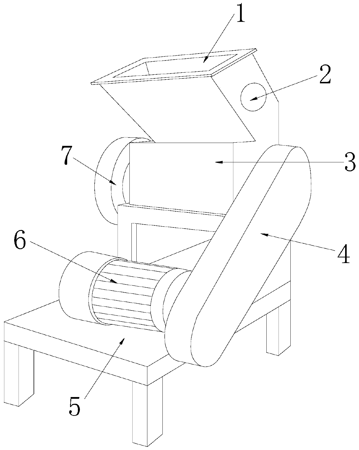
[0026] see Figure 1-Figure 5 , the present invention provides a rubber crushing device for rubber production, the structure of which includes a bucket 1, a crushing head 2, a filter bin 3, a protective cover 4, a fixed frame 5, a motor 6, and a moving wheel 7. The bucket 1 is installed on the filter On the bin 3, a protective cover 4 is provided on the side of the filter bin 3, and a moving wheel 7 is provided on the opposite side of the filter bin 3 to the protective cover 4, and the motor 6 is installed on the fixed frame 5, and the fixed frame 5 is provided with a filter chamber 3, and the bottom of the filter chamber 3 is provided with a crushing chamber, and the crushing chamber will directly output the crushed and screened rubber blocks from the opening;

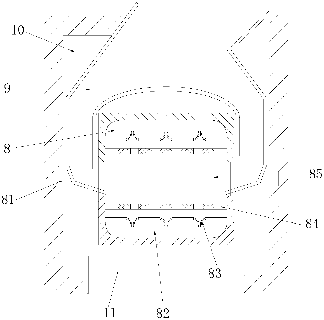
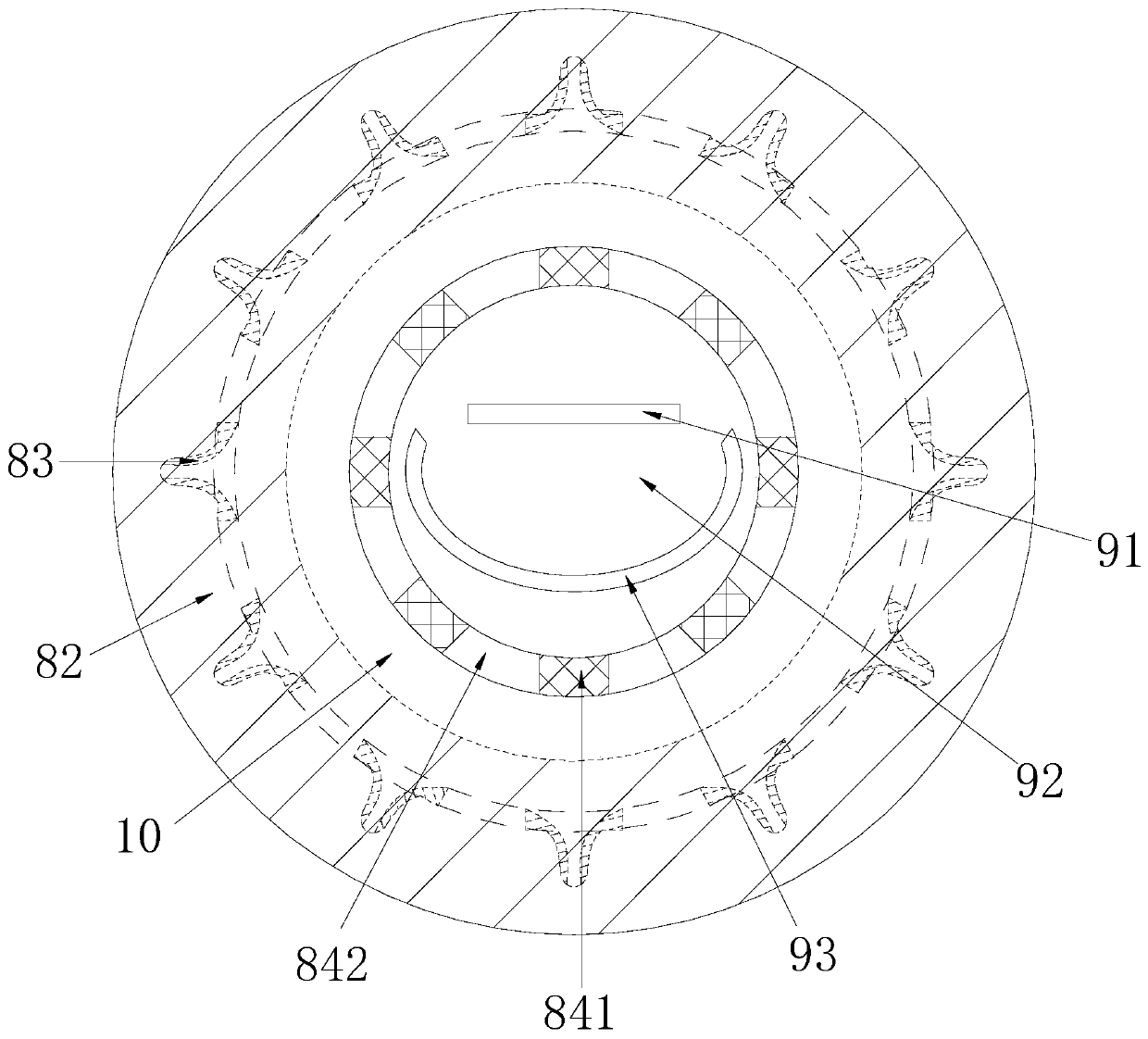
[0027] The filter bin 3 is composed of a screening device 8, a guiding bin 9, a working chamber 10, and an output port 11. The filtering device 8 communicates with the guiding bin 9, and the guiding bin 9 is connected...

Embodiment 2

[0037] see Figure 1-Figure 2 , Figure 5 , the present invention provides a rubber crushing device for rubber production, the structure of which includes a bucket 1, a crushing head 2, a filter bin 3, a protective cover 4, a fixed frame 5, a motor 6, and a moving wheel 7. The bucket 1 is installed on the filter On the bin 3, a protective cover 4 is provided on the side of the filter bin 3, and a moving wheel 7 is provided on the opposite side of the filter bin 3 to the protective cover 4, and the motor 6 is installed on the fixed frame 5, and the fixed frame 5 is provided with a filter chamber 3, and the bottom of the filter chamber 3 is provided with a crushing chamber, and the crushing chamber will directly output the crushed and screened rubber blocks from the opening; the filter chamber 3 is guided by a screening device 8, Bin 9, working chamber 10, and output port 11. The screening device 8 communicates with the guiding bin 9, and the guiding bin 9 is connected with the...


PUM


Abstract

The invention discloses a rubber crushing device for rubber production. The rubber crushing device structurally comprises a feed hopper, a crushing head, a filter bin, a protective cover, a fixing frame, a motor and a driving wheel, wherein the feed hopper is mounted on the filter bin, the protective cover is arranged on a side surface of the filter bin, the driving wheel is arranged on one side,opposite to the protective cover, of the filter bin, and the motor is mounted on the fixing frame. The rubber crushing device has the advantages that a cutter head is driven by an ejector rod to collide with a large-block-shaped plastic runway, the large-block-shaped plastic runway is cut, residual fine gravel and impurities are shaken off through impact force and guided into a main cavity througha guide bin to roll on a filter cartridge, and due to the fact that the mesh size of a mesh layer is smaller than the size of a rubber material crushed by the crushing head, thereby ensuring that theimpurities can pass through meshes and the rubber blocks cannot fall off; and through the arrangement of a one-way channel, recovered fine gravels and impurities in a collecting bin are prevented from falling back into the main cavity, it is guaranteed that the block-shaped plastic runway needing to be crushed in the next step does not contain impurities, and therefore the quality of recycled plastic is improved.

Description

technical field [0001] The invention relates to the field of rubber, in particular to a rubber crushing device for rubber production. Background technique [0002] The plastic runway is made of colored rubber particles. Rubber is a recyclable material. After use, the plastic runway will be partially scrapped, and some of the more complete rubber can be recycled. After recycling, it needs to be cleaned and then reused. Pulverize, the current rubber production rubber pulverizer has the following defects: [0003] The existing rubber crushing device directly washes and crushes the recovered rubber products, but for the plastic runway, impurities such as fine sand and gravel particles will still remain in the gaps between the rubber raised particles, and they will be directly thrown into the crushing In the warehouse, the rubber raw material will affect the overall quality due to the existence of impurities, and the fine sand and gravel particles will aggravate the wear of the ...

Claims


Application Information

Patent Timeline
IPC IPC(8): B29B17/04B29B17/02
CPCB29B17/02B29B17/04B29B2017/0224B29B2017/044Y02W30/52Y02W30/62
Inventor 周会文
Owner 周会文
Learn More