Numerical control longitudinal cutting device for non-interference cutter taking and use

A slitting device, non-interference technology, applied in packaging and other directions, can solve the problems of operation interference, complicated operation, and limited cutting products, and achieve the effect of high degree of automation and simplified operation control.

Pending Publication Date: 2020-08-04
浙江圣合机电科技有限公司
View PDF1 Cites 0 Cited by
  • Summary
  • Abstract
  • Description
  • Claims
  • Application Information

AI Technical Summary

Problems solved by technology

[0004] The technical purpose of the present invention is to provide a digitally controlled slitting device for taking and using knives without interference, s

Method used


Image

  • Numerical control longitudinal cutting device for non-interference cutter taking and use
  • Numerical control longitudinal cutting device for non-interference cutter taking and use
  • Numerical control longitudinal cutting device for non-interference cutter taking and use

Examples


Embodiment Construction

[0028] Below in conjunction with accompanying drawing, the present invention will be further described by specific embodiment:

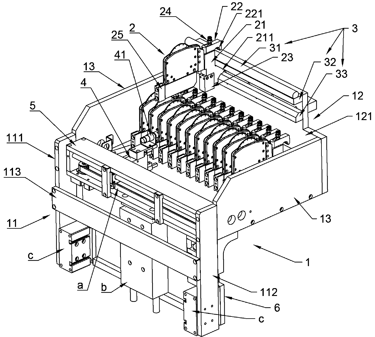
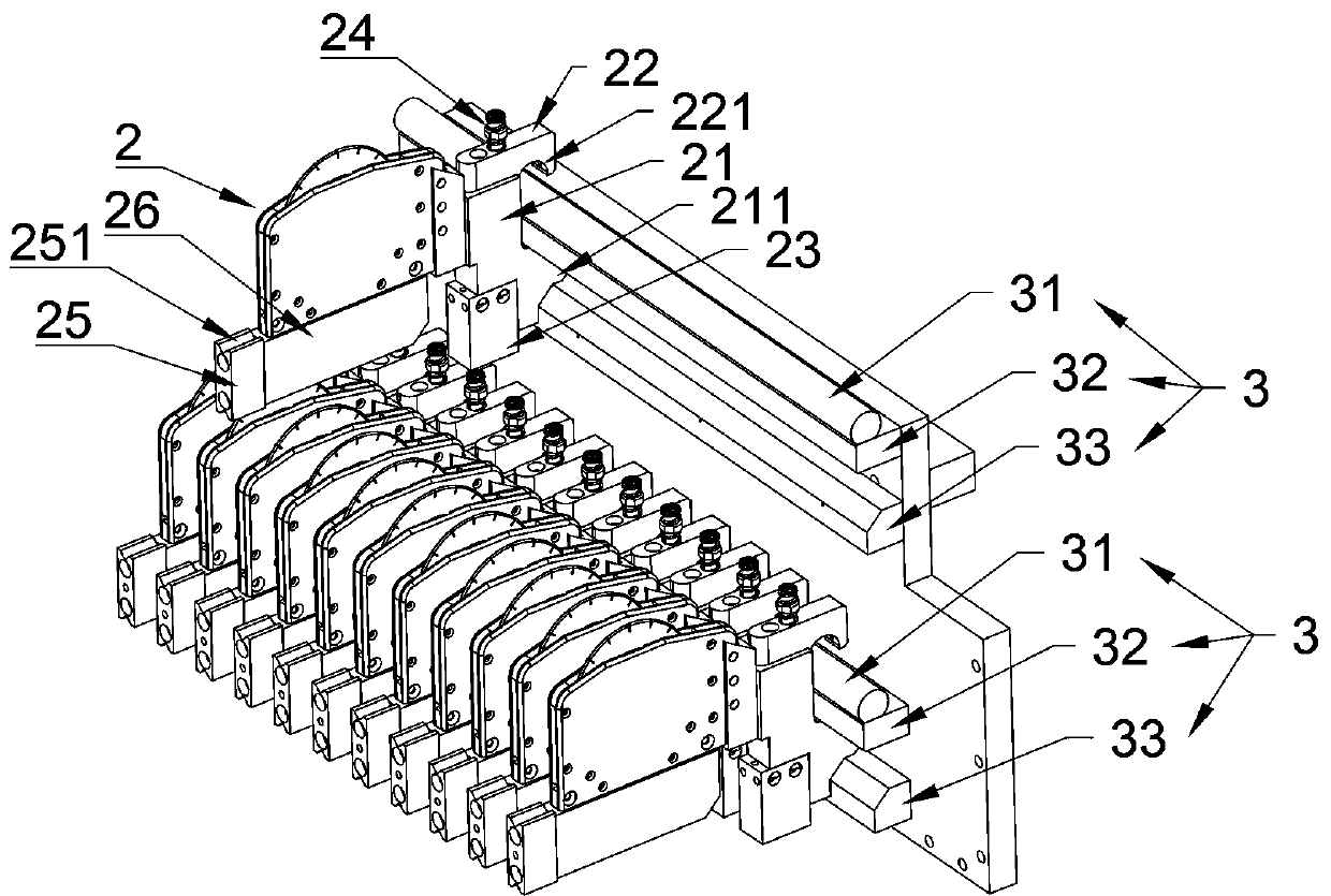
[0029] See figure 1, a CNC slitting device for picking and using knives without interference, including a frame 1, a number of floating hobs 2, a knife picking manipulator 4, a moving mechanism and two knife rests 3 (the two knife rests 3 are conventional and meet the requirements design, one as a cutting tool rest, and one as a parking tool rest), frame 1 includes a front frame 11 and a rear frame 12. Knife fetching manipulator 4 is connected on the moving mechanism, and moving mechanism is connected on the front frame 11 (moving mechanism also can be arranged separately, such as being installed on another mounting frame beside frame 1); Tool rest 3 is connected on rear frame 12, the floating hob 2 is connected with a hook mechanism and is hung on the frame 12 through the hook mechanism.

[0030] This embodiment figure 1 , figure 2 , Figure 4...


PUM


Abstract

A numerical control longitudinal cutting device for non-interference cutter taking and use comprises racks and a plurality of floating hobbing cutters, and also comprises a cutter taking manipulator,a movable mechanism and at least two cutter rests. The racks comprise the front rack and the rear rack, the cutter taking manipulator is connected to the movable mechanism, and the movable mechanism is independently arranged on or connected with the front rack; and the cutter rests are connected to the rear rack, and the floating hobbing cutters are connected with a clamping and hanging mechanismand are clamped and hung on the racks through the clamping and hanging mechanism. According to different cutting requirements, in a single cutting process, the floating hobbing cutters which are in use and stored are on different cutter rests and do not interfered with each other, there is an enough space for adjustment, the overall automation degree is higher, operation control is simpler, and more types of products can be correspondingly treated.

Description

technical field [0001] The invention relates to the technical field of packaging machine cutting, in particular to a numerically controlled slitting device for taking knives without interference. Background technique [0002] The working principle of the existing blister packaging machine: on the machine, the bottom film (plastic film) is clamped by the clip chain on both sides and brought into the machine; the driving of the machine makes the clip chain take a single-mode distance to bring the bottom film into the forming machine. Under the action of the mold, the packaging bottom film is formed into several cavities suitable for placing materials by heating and blistering under the action of the mold; the packaging bottom film enters the storage area, and the materials are put into the cavity of the packaging bottom film by manual or auxiliary machines ;The covering film (or paper) enters the machine and covers the opening surface of the cavity, and enters the sealing area...

Claims


Application Information

Patent Timeline
IPC IPC(8): B65B61/08
CPCB65B61/08
Inventor 胡少白金朝胡一乐
Owner 浙江圣合机电科技有限公司
Why Eureka
Try Eureka