Non-contact line parameter measurement system and measurement method

A line parameter and measurement system technology, applied in the measurement of electrical variables, electrical measurement, capacitance measurement and other directions, can solve the problems of insecurity, reduced efficiency, unadjustable lightning protection gap, etc., to achieve simple operation, reduce on-site operators, shorten the Effect of Line State Transition Time

Pending Publication Date: 2020-08-04
EXAMING & EXPERIMENTAL CENT OF ULTRAHIGH VOLTAGE POWER TRANSMISSION COMPANY CHINA SOUTHEN POWER GRID
View PDF1 Cites 1 Cited by
  • Summary
  • Abstract
  • Description
  • Claims
  • Application Information

AI Technical Summary

Problems solved by technology

[0003] In the current actual transmission line parameter measurement, there is no device or system that can provide the above functions. Operators often use simple ball gaps for manual adjustment, which requires frequent manual grounding, and needs to wear insulating gloves to touch the line on site. Gate equipment and measuring instruments are not safe, but also time-consuming and labor-intensive
In the prior art, the Chinese invention patent with the authorized announcement number CN103616537B discloses a lightning protection switching device and a method for measuring parameters. Manual switches are used to realize manual switching of different states of the line. There are discharge rods connected in parallel between the lines to achieve lightning protection. The operators at the measurement end and the state conversion end operate independently, which is inconvenient for communication and greatly reduces efficiency.
This technology also has the disadvantages of manual operation of the knife switch, non-adjustable lightning protection gap, and simple device. It is still time-consuming and labor-intensive in practical applications, and has potential safety hazards.

Method used


Image

  • Non-contact line parameter measurement system and measurement method
  • Non-contact line parameter measurement system and measurement method
  • Non-contact line parameter measurement system and measurement method

Examples


Embodiment Construction

[0034] The present invention will be described in detail below in conjunction with the accompanying drawings and specific embodiments, where the schematic embodiments and descriptions of the present invention are used to explain the present invention, but not to limit the present invention.

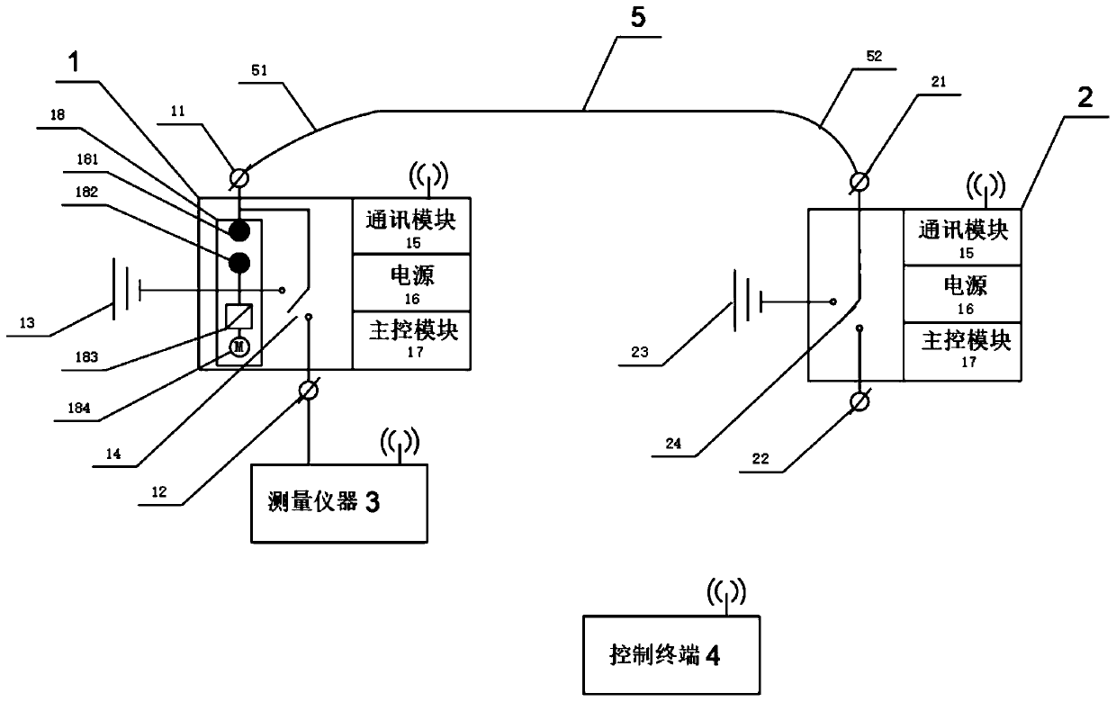
[0035] see figure 1 As shown, the present invention provides a non-contact line parameter measurement system, including a measurement terminal device 1, a state conversion terminal device 2, a measuring instrument 3 and a control terminal 4; the measurement terminal device 1 and the state conversion terminal device 2 are respectively connected to the The first down conductor 51 and the second down conductor 52 of the circuit 5 are tested.

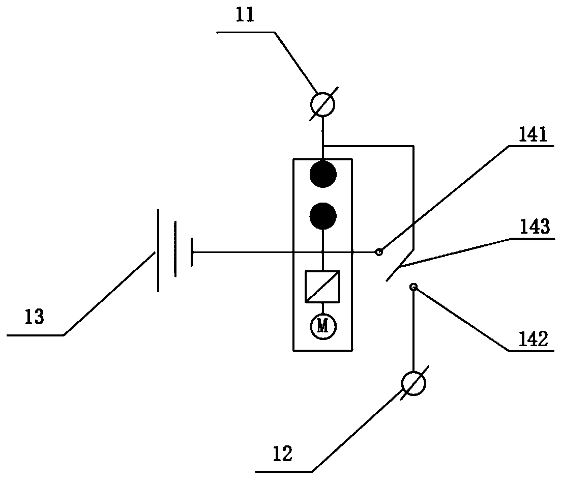
[0036] The measuring terminal device 1 includes a first incoming line terminal 11, a first outgoing line terminal 12, a first grounding terminal 13, a first switch 14, a communication module 15, a power supply 16, a main control module 17 and a lightni...


PUM


Abstract

The invention discloses a non-contact line parameter measurement system and measurement method. The system comprises a measuring end device, a line conversion end device, a measurement instrument anda control terminal. The measuring end device and the line conversion end device are respectively connected to a tested line end; the measurement instrument is connected to a wire outlet end of the measuring end device; and signals are transmitted between the control terminal and the measuring end device, the line conversion end device and the measurement instrument in a wireless communication mode. The measuring end device comprises a switch and a ball gap device. According to the invention, the test end module and the state conversion end module can be controlled in a non-contact manner by operating the control terminal, and line state switching is carried out safely and conveniently, so that line measurement operation is completed. The system is safe, convenient, simple to operate, labor-saving and high in working efficiency.

Description

technical field [0001] The invention belongs to the technical field of electric power system transmission line parameter measurement, and relates to a non-contact line parameter measurement system and a measurement method. Background technique [0002] Before the newly-built transmission line of the power system is put into operation, or during the regular maintenance of the line in operation, the line parameter measurement test is required. Line parameter measurement is to equivalent the line under test to resistance, capacitance, inductance and their combination, and measure the related values. The measurement of line parameter values ​​is the basis of line protection setting, fault location and power flow calculation. Generally, the lines under test on which line parameters are measured are at least 50 to 100 km long. At present, when measuring line parameters, the conversion and realization of various functions such as line grounding, short-circuiting, and suspension a...

Claims


Application Information

Patent Timeline
Patent Type & Authority Applications(China)
IPC IPC(8): G01R31/00G01R27/02G01R27/26
CPCG01R27/02G01R27/26G01R27/2605G01R31/00
Inventor 杨晓峰李士杰韦小星徐德增陆海熊锦州袁瑞敏张秋实韦清化何思靖魏向阳曾少豪
Owner EXAMING & EXPERIMENTAL CENT OF ULTRAHIGH VOLTAGE POWER TRANSMISSION COMPANY CHINA SOUTHEN POWER GRID
Why Eureka
Try Eureka