
Integrated IGBT (Insulated Gate Bipolar Translator) structure integrating light triggering and design method

A technology of light triggering and triggering control, applied in transistors, semiconductor devices, electrical components, etc., can solve problems such as IGBT insulation isolation problems

Active Publication Date: 2017-06-13
INST OF FLUID PHYSICS CHINA ACAD OF ENG PHYSICS
View PDF6 Cites 0 Cited by
  • Summary
  • Abstract
  • Description
  • Claims
  • Application Information

AI Technical Summary

Problems solved by technology

At the same time, when multiple IGBTs are used in series, the electric pulse trigger method will cause the insulation isolation problem of the IGBT

Method used


Image

  • Integrated IGBT (Insulated Gate Bipolar Translator) structure integrating light triggering and design method
  • Integrated IGBT (Insulated Gate Bipolar Translator) structure integrating light triggering and design method
  • Integrated IGBT (Insulated Gate Bipolar Translator) structure integrating light triggering and design method

Examples


Embodiment Construction

[0041] All the features disclosed in this specification, or all disclosed methods or steps in the process, except for mutually exclusive features and / or steps, can be combined in any manner.

[0042] Any feature disclosed in this specification, unless specifically stated, can be replaced by other equivalent or equivalent alternative features. That is, unless otherwise stated, each feature is just one example of a series of equivalent or similar features.

[0043] Related description of the invention:

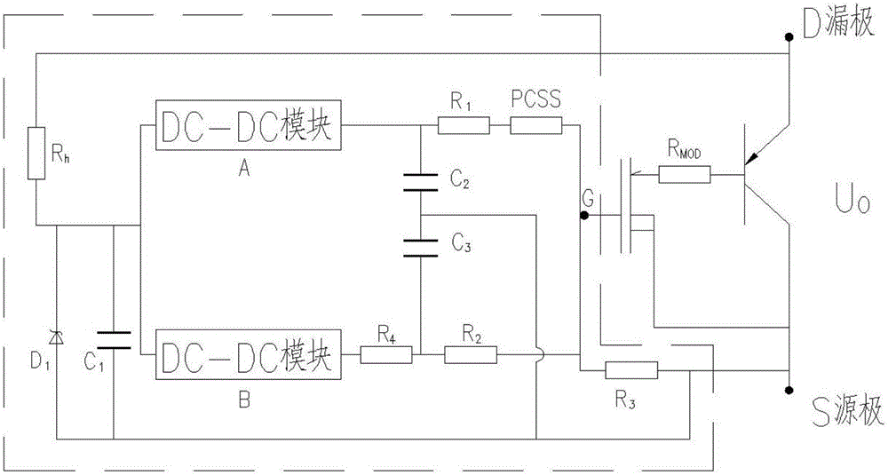
[0044] 1. Bleeding resistance R 3 Set between the IGBT gate and the source level, the function is to maintain a certain potential difference between the IGBT gate and the source, and avoid the uncertainty of the gate potential caused by the floating of the gate. Generally, this bias resistor R is set in the IGBT drive circuit 3 ;

[0045] 2. So far, the IGBT drive circuit and the IGBT device have adopted a discrete design method, that is, the IGBT drive circuit is a circuit board indep...


PUM


Abstract

The invention belongs to the field of design of semiconductor devices and in particular relates to an integrated IGBT (Insulated Gate Bipolar Translator) structure integrating light triggering and a design method. Aiming at the problems in the prior art, a triggering control primary power supply circuit and positive and negative polar grid electrode voltage control circuits, which are machined on the same silicon wafer of an IGBT circuit structure, are designed, and potential difference of a grid electrode relative to a source electrode is controlled by adopting an insulation isolation triggering method, so that on-off of the IGBT is controlled, and the problem of the IGBT that insulation isolation and state conversion time is long is solved. According to the integrated IGBT structure, when a light control switch of the positive polar grid electrode voltage control circuit is not illuminated, the negative polar grid electrode voltage control circuits is used for carrying out negative polar charging on an IGBT grid electrode, so that the IGBT keeps an off state; when the light control switch of the positive polar grid electrode voltage control circuit is illuminated, the positive polar grid electrode voltage control circuits is used for carrying out positive polar charging on the IGBT grid electrode; when voltage of the IGBT grid electrode reaches requirements of conducting control electric pulse parameters, the IGBT is conducted.

Description

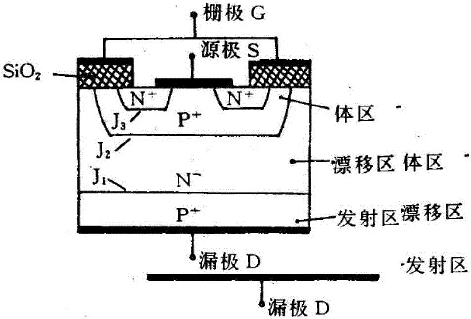
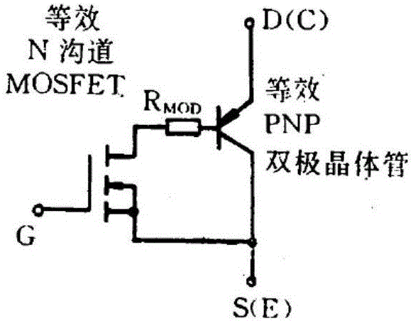
Technical field [0001] The invention belongs to the field of semiconductor device design, in particular to an integrated light-triggered integrated IGBT structure and design method. Background technique [0002] At present, IGBTs are designed as voltage control devices (Figure 1). The gate is a metal electrode. A sufficiently high forward driving voltage signal is applied between the gate and the source, and an inversion layer is formed in the P area under the gate. , That is, the N conduction channel, through this channel, electrons are injected from the N+ region under the source into the N- region, so that the IGBT enters the conduction state. When the forward driving voltage between the gate and the source disappears and the potential difference between the gate and the source is lower than the voltage threshold required for the IGBT to be turned on, the IGBT is turned off. Therefore, the current IGBT conduction is controlled by the gate drive voltage signal forming an N-typ...

Claims


Application Information

Patent Timeline
Patent Type & Authority Applications(China)
IPC IPC(8): H03K17/567H03K17/041
CPCH03K17/04113H03K17/567H03K2217/0054H03K2217/0081Y02B70/10
Inventor 赵娟李博婷李洪涛黄宇鹏李波张信
Owner INST OF FLUID PHYSICS CHINA ACAD OF ENG PHYSICS
Learn More