
Oil-immersed capacitor unit structure for locomotive roof

A capacitor unit, capacitor technology, applied in the direction of capacitors, electrical components, etc., can solve the problems of high-intensity vibration, high-voltage capacitors, etc., and achieve the effect of high-intensity vibration amplitude

Pending Publication Date: 2020-08-04
HERONG ELECTRIC
View PDF0 Cites 0 Cited by
  • Summary
  • Abstract
  • Description
  • Claims
  • Application Information

AI Technical Summary

Problems solved by technology

[0004] The purpose of the present invention is to provide an oil-immersed capacitor unit structure for the locomotive roof, which solves the problems of high voltage and high-intensity vibration that the capacitor bears during the operation of the locomotive and the need to filter out a certain channel signal during the operation

Method used


Image

  • Oil-immersed capacitor unit structure for locomotive roof
  • Oil-immersed capacitor unit structure for locomotive roof

Examples


Embodiment Construction

[0020] The present invention will be described in detail below in conjunction with the accompanying drawings and specific embodiments.

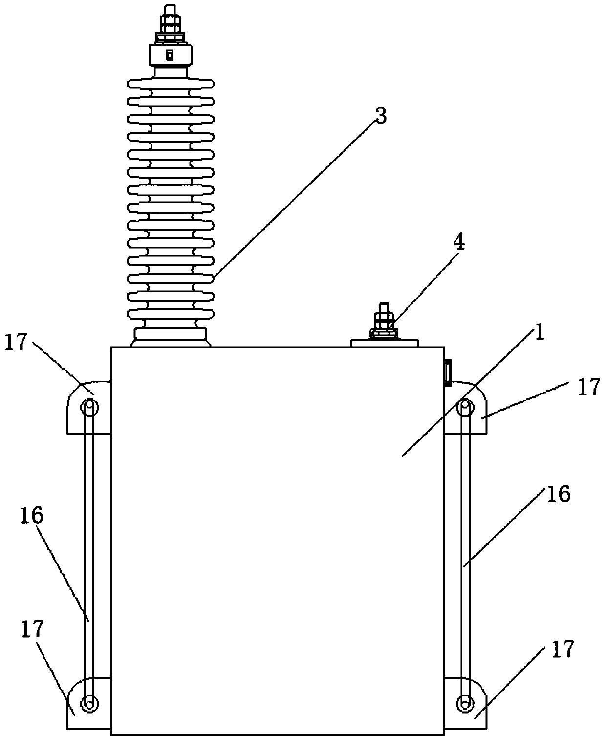
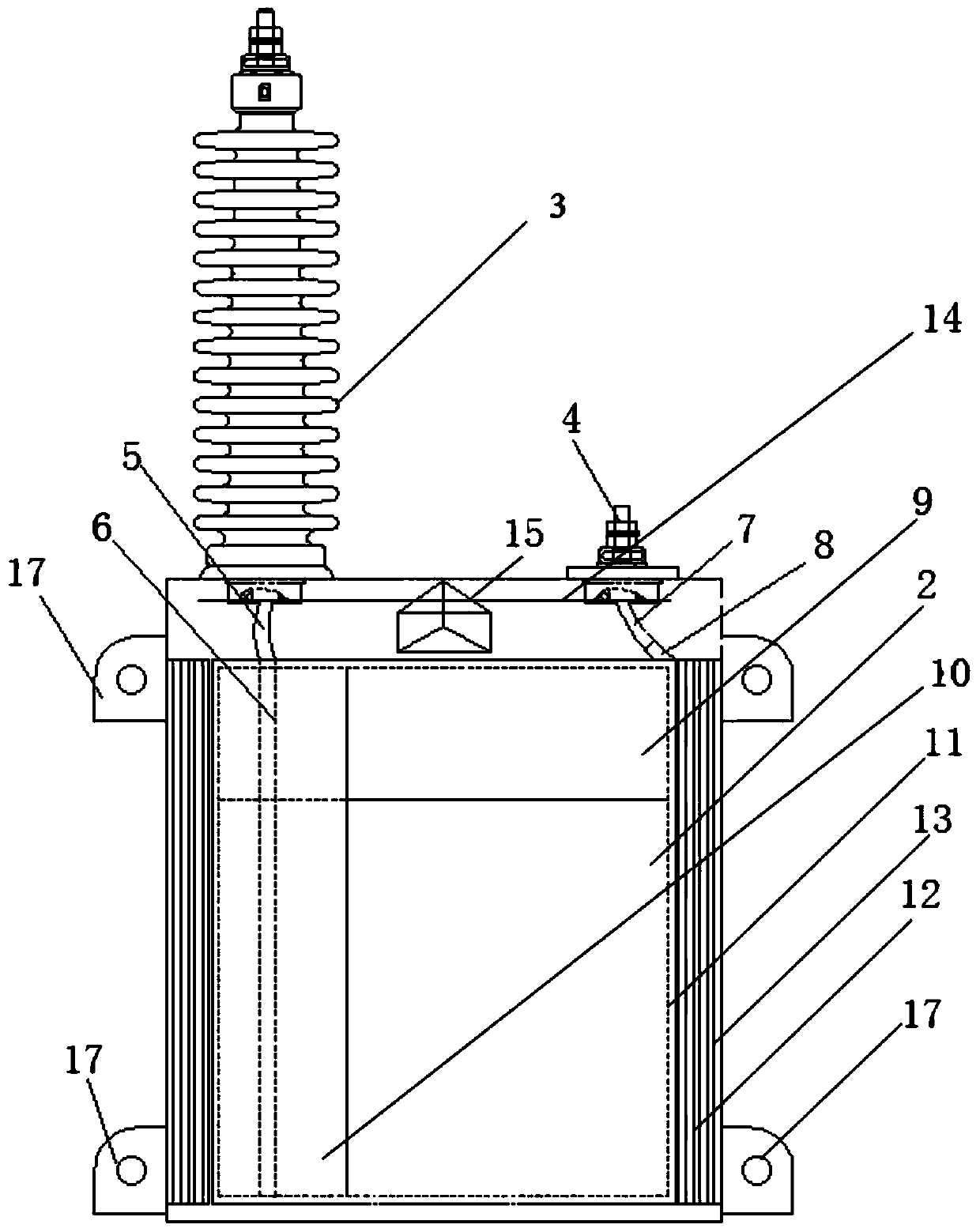
[0021] A kind of oil-immersed capacitor unit structure for locomotive roof of the present invention, as figure 1 , 2 As shown, it includes a capacitor case 1, and the inside of the capacitor case 1 is provided with a capacitor core 2, and the upper end of the capacitor case 1 is respectively provided with a capacitor bushing 3 and a grounding terminal 4, and the capacitor bushing 3 is connected to the Connect piece A6, connecting piece A6 is connected to the outlet end of capacitor core 2; grounding terminal 4 is connected to connecting piece B8 through bushing tail wire B7, connecting piece B8 is connected to the incoming line end of capacitor core 2, capacitor core 2 is covered with a U-shaped liner 9, and the U-shaped liner 9 covers the top surface and the front and rear sides of the capacitor core 2 respectively;

[0022] The left side ...


PUM


Abstract

The invention discloses an oil-immersed capacitor unit structure for a locomotive roof, and the structure comprises a capacitor core. A U-shaped auxiliary package is disposed on the left side surfaceof the capacitor core, and two ends of the auxiliary package respectively extend to the front and rear side surfaces of the capacitor core after the auxiliary package wraps the left side surface of the capacitor core; a connecting sheet A is located at the outer side of the auxiliary package, and the auxiliary package isolates the connecting sheet A from the capacitor core; an outer package is wound outside the auxiliary package; the connecting piece A is wrapped inside the outer package, and the periphery and the bottom of the capacitor core are wound by the outer package; a filling paperboard and an auxiliary outer package are sequentially wound between the outer package and the capacitor shell; and the periphery of the capacitor core is wrapped by the filling paperboard and the auxiliary outer package. The problems that the capacitor bears high-voltage and high-strength vibration in the running process of a locomotive and a signal of a certain channel needs to be filtered out in therunning process are solved.

Description

technical field [0001] The invention belongs to the technical field of power capacitor units, and relates to an oil-immersed capacitor unit structure for a locomotive roof. Background technique [0002] The capacitor is composed of several parts such as the core, the shell, and the outlet porcelain sleeve. There are hanging plates on both sides of the box wall for installation, and the grounding bolts are installed on one side of the hanging plate. The shell is formed and welded by stainless steel plates. [0003] The rated voltage of a single capacitor commonly used in domestic substations is generally <10kV, and the withstand voltage between terminals is 2.15U N , there is no special requirement for the anti-seismic performance of a single capacitor. The unit voltage of the capacitor used on the locomotive roof is 40kV. During the operation process, the signal of a certain frequency band needs to be filtered out, and it must be able to withstand high voltage and vibrati...

Claims


Application Information

Patent Timeline
Patent Type & Authority Applications(China)
IPC IPC(8): H01G2/10H01G2/04H01G2/00
CPCH01G2/04H01G2/106H01G2/00
Inventor 姚妍君肖果孙晓凤王刚李大燕解冲孙达屈媛
Owner HERONG ELECTRIC
Learn More