Festive lantern driving system based on PLC-BUS technology

A PLC-BUS and drive system technology, applied in the field of Internet of Things (IOT), can solve the problems of lack of user effects, smart lights without voice-activated color adjustment, and clumsy color changes, so as to enhance control diversity and reduce the impact of light color , Enhance the effect of environmental adaptability

Pending Publication Date: 2020-08-04
SHENZHEN HAILING TECH CO LTD +1
View PDF11 Cites 0 Cited by
  • Summary
  • Abstract
  • Description
  • Claims
  • Application Information

AI Technical Summary

Problems solved by technology

[0004] However, the current intelligent lighting system generally has a lantern structure on the smart lamp, which is used to make the lamp emit various colors, but the smart lamp does not have the function of voice-activated color adjustment, and the corresponding adjustment is generally carried out through the panel. Color adjustment. In addition, the existing smart lights do not adjust well in combination with the surrounding environment, but only clumsily perform relevant color changes according to the instructions input by the user through the panel, which often fails to achieve the desired effect of the user.

Method used


Image

  • Festive lantern driving system based on PLC-BUS technology
  • Festive lantern driving system based on PLC-BUS technology

Examples


Embodiment 1

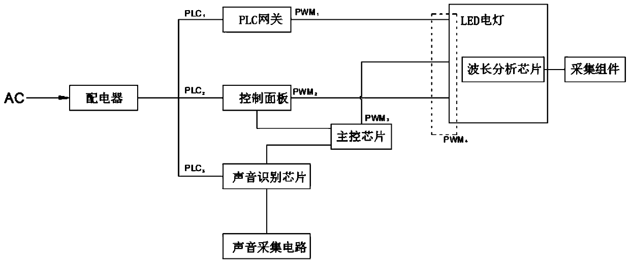
[0044] Embodiment 1, the PLC gateway is connected to the wifi router, the wifi router is wirelessly connected to the user terminal (such as a mobile phone and other smart devices), the user terminal transmits the light adjustment instruction to the PLC gateway through the wifi router, and the PLC gateway corresponds to the light adjustment instruction according to the PLC line transmission It can be understood that there is an APP on the user terminal, and the user can directly input instructions through virtual buttons (finally the power carrier is transmitted to the control panel), and the user can also input voice through the APP ( Finally, the power carrier signal is transmitted to the voice recognition chip).

[0045] The above-mentioned sound recognition chip is connected with the sound collection circuit, therefore,

Embodiment 2

[0046] Embodiment 2, the user can directly output the voice signal in the preset space in the family, the voice acquisition circuit collects the voice signal, then the voice recognition chip acquires the voice signal and recognizes it, converts the voice signal into text data in txt format, and then Send text data in the form of txt to the main control chip.

[0047] The above-mentioned control panel is connected with the main control chip, that is, after the control panel receives the power carrier signal transmitted by the PLC gateway through the PLC circuit, it sends the control signal corresponding to the power carrier signal to the main control chip; in addition, the above-mentioned control panel directly Connected with the LED lamp, the control panel directly outputs the control signal to the LED lamp, so that the LED lamp can adjust the corresponding light color.

[0048] The above-mentioned PWM circuit is respectively connected to the other end of the PLC gateway and t...


PUM


Abstract

The invention provides a festive lantern driving system based on PLC-BUS technology. One end of a power distributor is connected to the mains supply, and the other end of the power distributor is connected to a PLC circuit to supply power; the PLC circuit is connected to one end of a PLC gateway, one end of a control panel and one end of a voice recognition chip so as to achieve the transmission of PLC-BUS power carrier signals. The PWM circuit is connected to the other end of the PLC gateway and the other end of the control panel and connected to a main control chip, and the main control chipis connected with the voice recognition chip and the control panel so that the main control chip, the voice recognition chip and the control panel can transmit control signals. The voice recognitionchip is connected with a voice acquisition circuit so as to receive a voice signal output by a user; the PWM circuit is further connected to an LED electric lamp, a wavelength analysis chip is arranged in the LED electric lamp, and the wavelength analysis chip is connected with an acquisition assembly arranged outside the LED electric lamp so as to reduce the influence of ambient light on the light color of the LED electric lamp.

Description

technical field [0001] This application relates to the technical field of the Internet of Things (IOT), in particular to a lantern driving system based on PLC-BUS technology. Background technique [0002] PLC-BUS technology (PulsePositionModulation (PPM)) is a new power carrier communication technology developed in recent years, referred to as pulse phase modulation method. It uses the sine wave of the power line as a synchronous signal, and sends instantaneous electrical pulses in four fixed timings to transmit signals; PLC-BUS signals can be transmitted very far, and PLC-BUS signals can be transmitted in an office environment without any electrical appliances. Each floor is about 1000 square meters, which can be easily transferred to any corner of the 30 floors. In the office environment with electrical appliances installed, each floor is about 1,000 square meters, which can be easily transferred to any corner of the 15 floors. Due to the particularity of the PPM communi...

Claims


Application Information

Patent Timeline
IPC IPC(8): H05B45/325H05B45/22H05B47/185G10L15/22G10L15/18
CPCH05B45/325H05B45/22H05B47/185G10L15/22G10L15/1822G10L2015/223
Inventor 陈志林杨明华刘新怡罗聪石厅弟罗亮李剑方君吴雅晖周力大刘恋贺明牛博金通曹赛祎章波朱娴王抒郑博文林灏刘男周雪瑶梁连山戴超魏刚张福清姜江周淼严定传战永隆李红卫舒艳华尤中海
Owner SHENZHEN HAILING TECH CO LTD
Why Eureka
Try Eureka