Lens barrel and image pickup device
A lens and lens barrel technology, which is applied in the field of fixed optical components, can solve the problems of impact sound, impact transmission to hands, and obvious garbage.
- Summary
- Abstract
- Description
- Claims
- Application Information
AI Technical Summary
Problems solved by technology
Method used
Image

Examples
no. 1 Embodiment approach
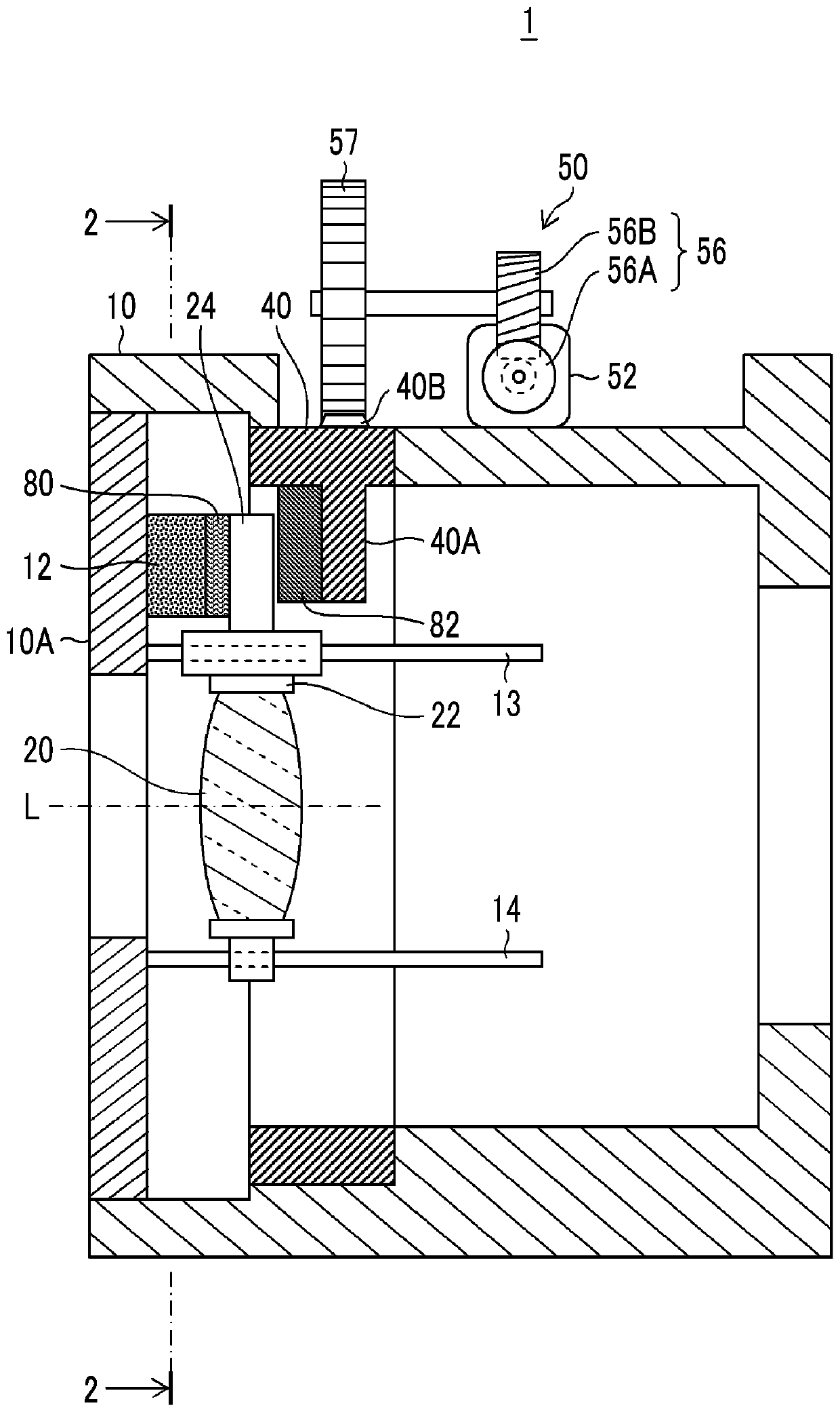
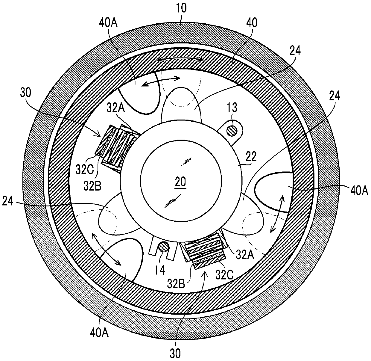
[0081] figure 1 It is a sectional view of the main part showing the first embodiment of the lens barrel according to the present invention, figure 2 is along figure 1 Cutaway view of line 2-2 shown.
[0082] In this example, figure 1 and figure 2 The illustrated lens barrel 1 functions as a fixed focus interchangeable lens of an interchangeable lens camera having an auto focus (Auto Focus / AF) function.
[0083] The lens barrel 1 is mainly composed of a fixed frame 10 , a movable frame 22 that holds an optical component (focusing lens) 20 , a voice coil motor (VCM: Voice Coil Motor) 30 , which is a type of linear motor that drives the movable frame 22 , and limited Movement restriction portion 12 of movable frame 22 , engagement portion 24 provided in movable frame 22 , lock ring 40 functioning as a locking member for fixing (locking) movement of movable frame 22 , and movement of lock ring 40 A (rotating) electric actuator 50 is constituted.
[0084] The main shaft 13 ...
no. 2 Embodiment approach
[0135] Figure 5 It is a perspective view showing a second embodiment of the lens barrel according to the present invention. In addition, with figure 1 and figure 2 The parts common to the lens barrel 1 of the first embodiment shown are denoted by the same reference numerals, and detailed descriptions thereof will be omitted.
[0136] Figure 5 The lens barrel 1 - 2 of the second embodiment shown is different from the first embodiment in that a locking member 40 - 2 is mainly used instead of the lock ring 40 and an abutment member 70 is added.
[0137] Like the lock ring 40 , the locking member 40 - 2 is rotatably supported with respect to the fixed frame 10 about the optical axis L of the focus lens 20 , but is not formed in a ring shape but in an arc shape.
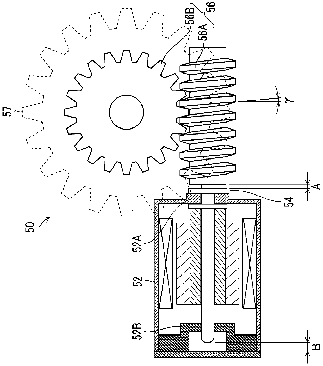
[0138] Image 6 It is a perspective view of the electric actuator 50 applied to the lens barrel 1-2 of the second embodiment.
[0139] Image 6 The spur gear 57 of the gear train of the electric actuator 50 show...
no. 3 Embodiment approach
[0148] Figure 9 and Figure 10 are perspective views each showing a third embodiment of the lens barrel according to the present invention, Figure 9 shows about the unlocked state, Figure 10 The lock state is shown. In addition, the same code|symbol is attached|subjected to the part common to the lens barrel of 1st Embodiment and 2nd Embodiment, and the detailed description is abbreviate|omitted.
[0149] Figure 9 and Figure 10 The main locking member 40-3 of the lens barrel 1-3 of the illustrated third embodiment is different from the locking member 40-2 of the lens barrel 1-2 of the second embodiment.
[0150] like Figure 9 and Figure 10As shown, the locking member 40 - 3 of the lens barrel 1 - 3 of the third embodiment is rotatably supported around a rotation axis parallel to an optical axis different from the optical axis of the optical member (focus lens 20 ).
[0151] The locking member 40 - 3 is locked by the rotational driving force applied from the elec...
PUM
 Abstract
Description
Claims
Application Information
 - R&D
- Intellectual Property
- Life Sciences
- Materials
- Tech Scout
- Unparalleled Data Quality
- Higher Quality Content
- 60% Fewer Hallucinations
Browse by: Latest US Patents, China's latest patents, Technical Efficacy Thesaurus, Application Domain, Technology Topic, Popular Technical Reports.
© 2025 PatSnap. All rights reserved.Legal|Privacy policy|Modern Slavery Act Transparency Statement|Sitemap|About US| Contact US: help@patsnap.com