Tooling for a spline shaft and using method thereof
A spline shaft and tooling technology, which is applied in the field of tooling for spline shafts, can solve problems such as troublesome fixing, and achieve the effects of improving stability, improving processing efficiency and simplifying fixing steps.
- Summary
- Abstract
- Description
- Claims
- Application Information
AI Technical Summary
Problems solved by technology
Method used
Image
Examples
Embodiment 1
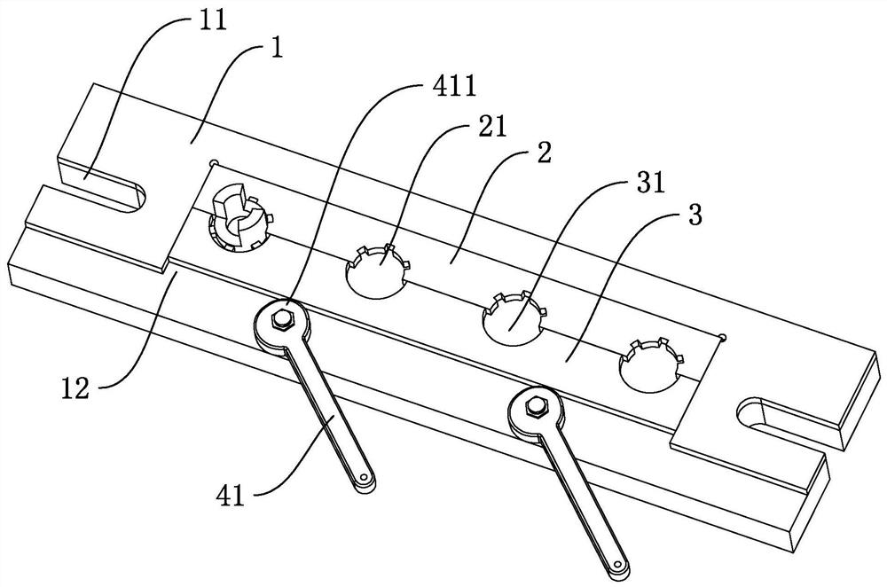
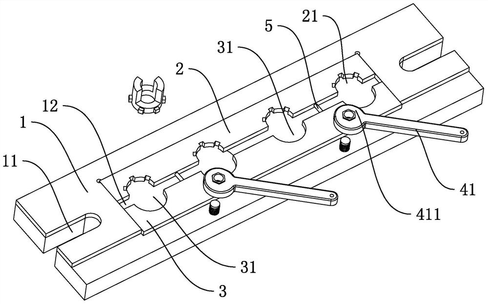
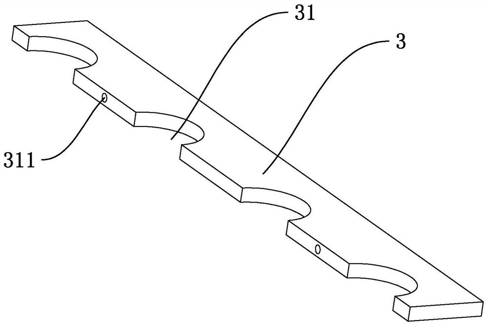
[0045] like figure 1 and figure 2As shown, a tooling for a spline shaft includes a mounting plate 1 that is similar to a rectangular parallelepiped. Both ends of the mounting plate 1 in the length direction are provided with mounting grooves 11 for mounting on a processing machine tool. The middle part of the mounting plate 1 is fixed with a rectangular parallelepiped. The clamping plate 2 is provided with a plurality of spline gaps 21 on the long side of the clamping plate 2 for snap-fitting with the protrusions on the spline shaft. In this embodiment, there are four spline gaps 21 . A rectangular sliding groove 12 is provided on the mounting plate 1, and a rectangular parallelepiped abutting plate 3 is slidably provided in the sliding groove 12. The long side of the abutting plate 3 close to the clamping plate 2 is provided with an abutting flower. The abutting notch 31 on the radially outermost side wall of the key shaft, and the number and position of the abutting notch...
Embodiment 2
[0052] like Figure 4 and Figure 5 As shown, a tooling for a spline shaft differs from Embodiment 1 in that:
[0053] The drive group assembly also includes extension springs 42, two extension springs 42 are provided, the mounting plate 1 is located on the side of the abutment plate 3 away from the clamping plate 2, and an insertion groove 13 is provided, and there are two insertion grooves 13, two insertion grooves 13 The length direction of the grooves 13 is parallel to the sliding direction of the abutment plate 3, and the two embedding grooves 13 are arranged symmetrically along the length direction of the mounting plate 1. Two extension blocks 32 are provided. The two extension blocks 32 are respectively embedded in the two insertion grooves 13 , and the corresponding two tension springs 42 are respectively embedded in the two insertion grooves 13 .
[0054] Since the structures and installation methods of the two tension springs 42 are the same, any one of the two ten...
Embodiment 3
[0058] like Image 6 As shown, a tooling for a spline shaft differs from Embodiment 1 in that:
[0059] The drive assembly 4 includes a linear cylinder 43, which is fixed on the mounting plate 1, and the linear cylinder 43 is located in the middle of the abutment plate 3, and the end of the piston rod of the linear cylinder 43 is fixed with a concave connecting plate 6 by bolts, The abutment plate 3 is fixed on the opening end of the connecting plate 6 , and the movement direction of the piston rod of the linear cylinder 43 is parallel to the sliding direction of the abutment plate 3 .
[0060] The method of using the tooling will be further elaborated below in conjunction with specific actions: In actual use, the linear cylinder 43 is used to directly drive the abutment plate 3 to slide on the mounting plate 1 along the direction close to the clamping plate 2 and away from the clamping plate 2, high degree of automation.
PUM
 Abstract
Description
Claims
Application Information
 - R&D
- Intellectual Property
- Life Sciences
- Materials
- Tech Scout
- Unparalleled Data Quality
- Higher Quality Content
- 60% Fewer Hallucinations
Browse by: Latest US Patents, China's latest patents, Technical Efficacy Thesaurus, Application Domain, Technology Topic, Popular Technical Reports.
© 2025 PatSnap. All rights reserved.Legal|Privacy policy|Modern Slavery Act Transparency Statement|Sitemap|About US| Contact US: help@patsnap.com


