Directly-buried heat preservation pipeline installing construction method

A technology for thermal insulation pipelines and construction methods, which is applied in the directions of lifting devices, transportation and packaging, conveyors, etc., can solve the problems that the movement states cannot be independent of each other, the transportation mechanism is easily damaged, and the pipeline connection is difficult, etc. The difficulty of docking and the effect of ensuring concentricity

Active Publication Date: 2020-08-07
CHINA RAILWAY 22ND BUREAU GROUP +2
View PDF11 Cites 4 Cited by
  • Summary
  • Abstract
  • Description
  • Claims
  • Application Information

AI Technical Summary

Problems solved by technology

[0003] However, the installation and construction methods of direct-buried thermal insulation pipelines in the current market have the following problems in the operation process: a. Since the docking mechanism in the traditional direct-buried thermal insulation pipeline installation and construction method is in operation, the concentricity between the butt pipes needs to be manually controlled, resulting in The docking of the pipeline is difficult. At the same time, when the docking mechanism drives the pipeline to move laterally, the weight of the pipeline itself is completely applied to the upper end of the transportation mechanism, making the transportation mechanism easy to damage; b. The docking mechanism in the traditional direct buried thermal insulation pipeline installation construction method When docking multiple pipes, under the action of the same driving source, the motion states of the pipes cannot be independent of each other, that is, the feed between the pipes at the same time

Method used


Image

  • Directly-buried heat preservation pipeline installing construction method
  • Directly-buried heat preservation pipeline installing construction method
  • Directly-buried heat preservation pipeline installing construction method

Examples


Embodiment Construction

[0031] In order to make the technical problems, technical solutions and beneficial effects to be solved by the present invention clearer, the present invention will be further described in detail below in conjunction with the accompanying drawings and embodiments. It should be understood that the specific embodiments described here are only used to explain the present invention, not to limit the present invention.

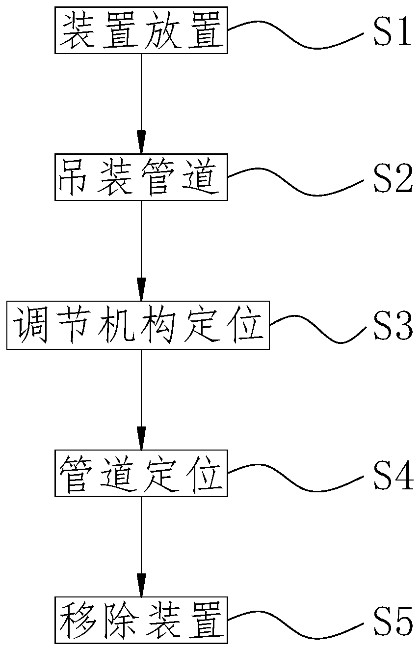
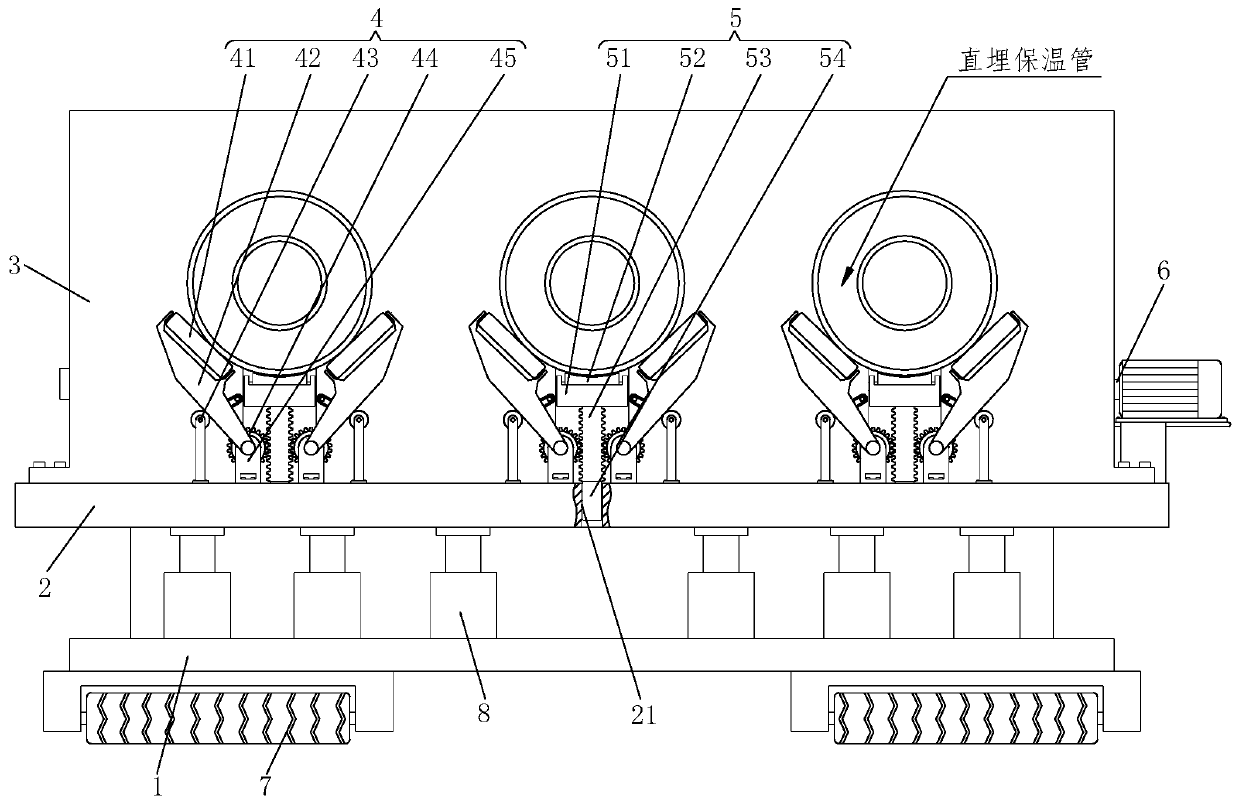
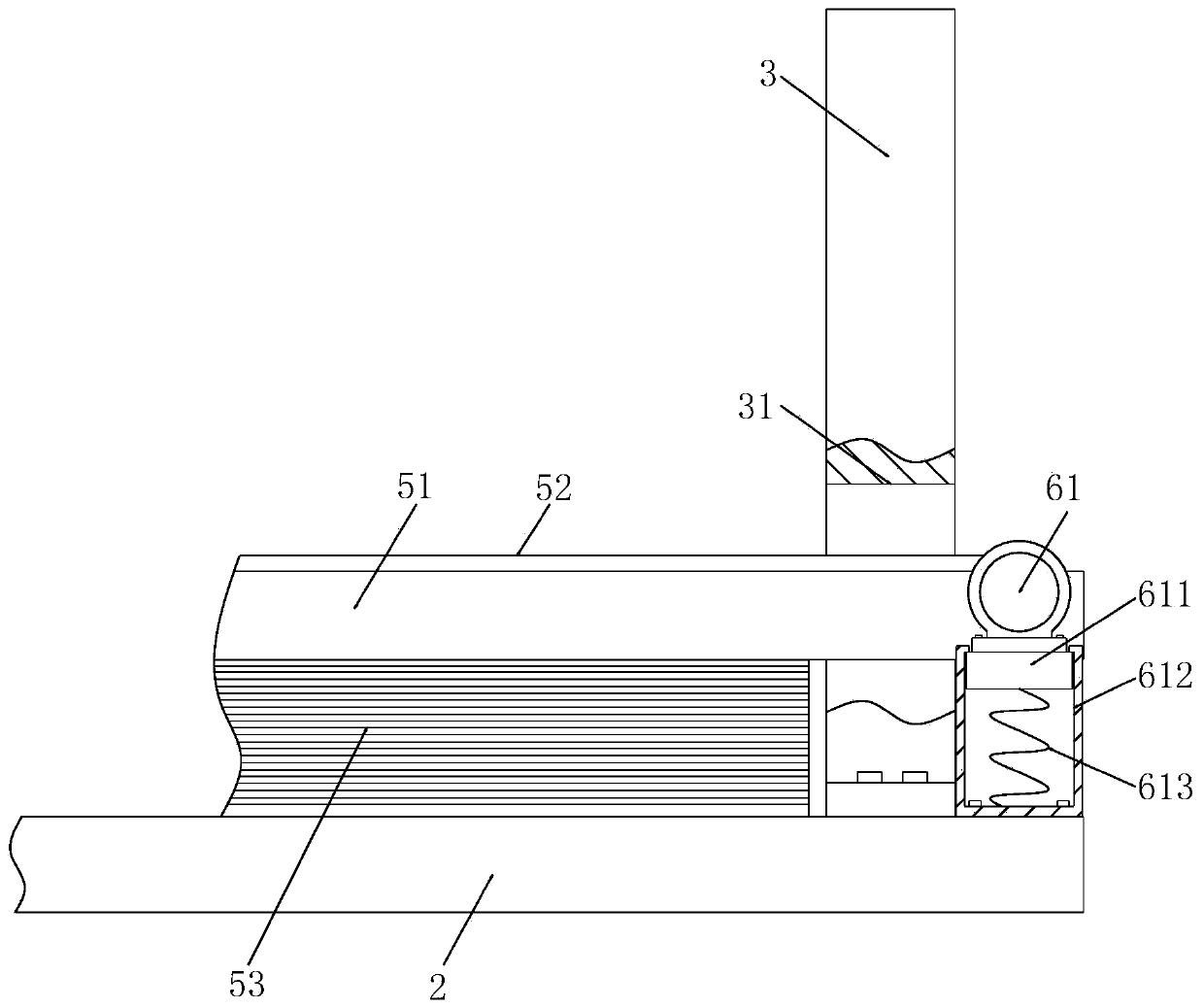
[0032] Refer to 1-7, a method for installing a direct buried thermal insulation pipeline, which uses a direct buried thermal insulation pipeline installation and construction device, the direct buried thermal insulation pipeline installation and construction device includes a fixed base 1, a rectangular plate 2, and a mounting plate 3 , support structure 4, adjustment mechanism 5, drive mechanism 6, movable wheel 7 and hydraulic push rod 8, the specific method when using the above-mentioned direct-buried thermal insulation pipeline installation and construction devi...


PUM


Abstract

The invention relates to a directly-buried heat preservation pipeline installing construction method. A fixing base, a rectangular plate, an installing plate, supporting structures, adjusting mechanisms, a drive mechanism, movable wheels and hydraulic push rods are included. The movable wheels are arranged at the bottom of the fixing base. The hydraulic push rods are arranged on the top of the fixing base. The rectangular plate is connected to the tops of the hydraulic push rods. The installing plate is arranged on one side of the top of the rectangular plate. The supporting structures are arranged on the upper end face of the rectangular plate at equal interval. Rectangular displacement holes are formed in the installing plate at equal interval. Each rectangular displacement hole is internally provided with the corresponding adjusting mechanism, wherein one end of the adjusting mechanism is connected with the drive mechanism. The connected positions of the interior of the rectangularplate and the adjusting mechanisms are provided with positioning rectangular holes. Hinge bases are symmetrically arranged on the upper end face of the rectangular plate. Rotation shafts are arrangedon the tops of the hinge bases. Gears are welded to the positions, located in the hinge bases, of the outer walls of the rotation shafts. The directly-buried heat preservation pipeline installing construction method has the characters that the butt-joint difficulty is low, the service life is long, and practicability is high.

Description

technical field [0001] The invention relates to the technical field of installation and construction of thermal insulation pipelines, in particular to a method for installation and construction of directly buried thermal insulation pipelines. Background technique [0002] Directly buried thermal insulation pipes are mainly divided into two types: plastic sheathed steel prefabricated thermal insulation pipes and steel sheathed steel thermal insulation pipes. Among them, the steel-sheathed steel insulation pipe is composed of an outer protective steel pipe plus steel pipe anticorrosion, a polyurethane foam insulation layer and an inner working steel pipe, or an airgel thermal insulation felt plus polyurethane high-pressure foam composite scheme. When installing the steel-sleeved steel insulation pipe, since the joints of the pipes are fixed by welding, before welding the pipes, the joints between the pipes must be completely overlapped under the action of the pipe butt joint m...

Claims


Application Information

Patent Timeline
Patent Type & Authority Applications(China)
IPC IPC(8): B66F7/16B66F7/28B65G15/32B65G15/58B65G23/04
CPCB65G15/32B65G15/58B65G23/04B65G2201/0276B66F7/16B66F7/28
Inventor 王辉毛淑南
Owner CHINA RAILWAY 22ND BUREAU GROUP
Why Eureka
Try Eureka