Method for producing a MEMS structure and corresponding MEMS structure

A structure and functional layer technology, applied in the manufacture of microstructure devices, processes for producing decorative surface effects, microstructure technology, etc., can solve problems such as unfavorable process steps, inability to remove oxides, etc., and achieve high process flexibility. The effect of stable and tight, effective and rapid construction of closed areas

Pending Publication Date: 2020-08-07
ROBERT BOSCH GMBH
View PDF4 Cites 0 Cited by
  • Summary
  • Abstract
  • Description
  • Claims
  • Application Information

AI Technical Summary

Problems solved by technology

However, since the closed region is located above the through-opening and the oxide located there cannot be removed, a very high topography results on the surface, which is disadvantageous for further process steps.

Method used


Image

  • Method for producing a MEMS structure and corresponding MEMS structure
  • Method for producing a MEMS structure and corresponding MEMS structure
  • Method for producing a MEMS structure and corresponding MEMS structure

Examples


Embodiment Construction

[0057] In the drawings, the same reference numerals are used to indicate the same or the same elements.

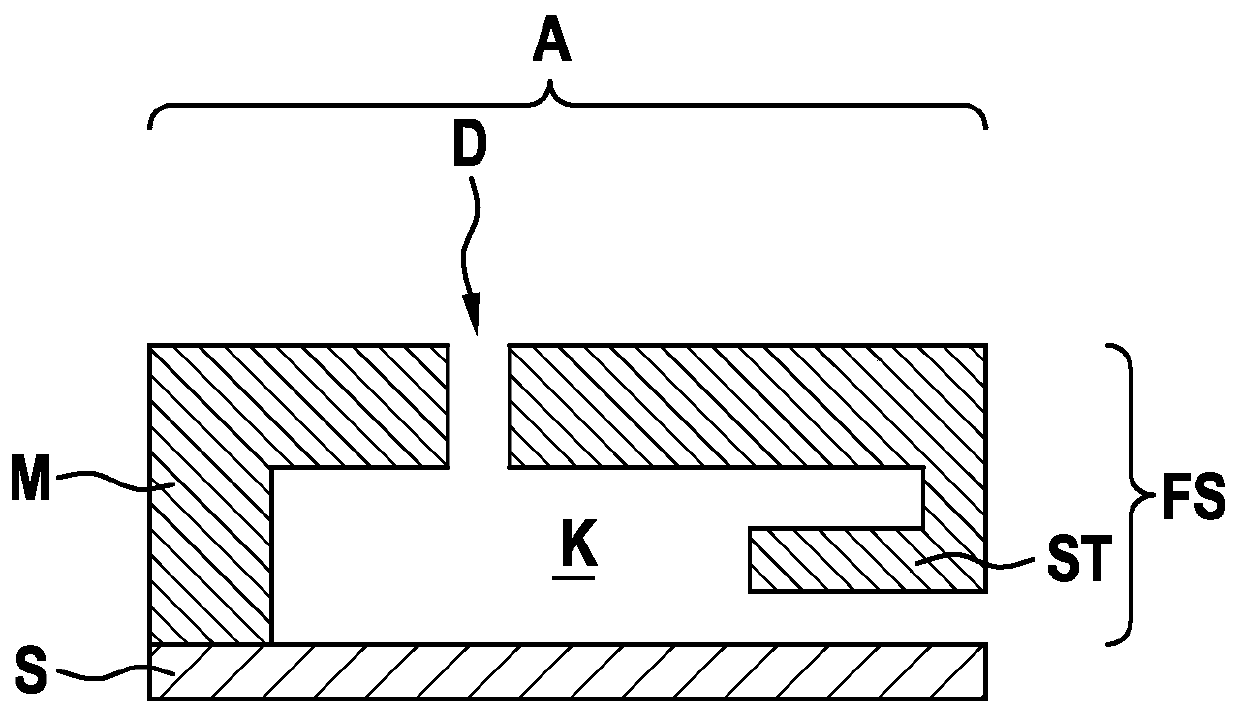
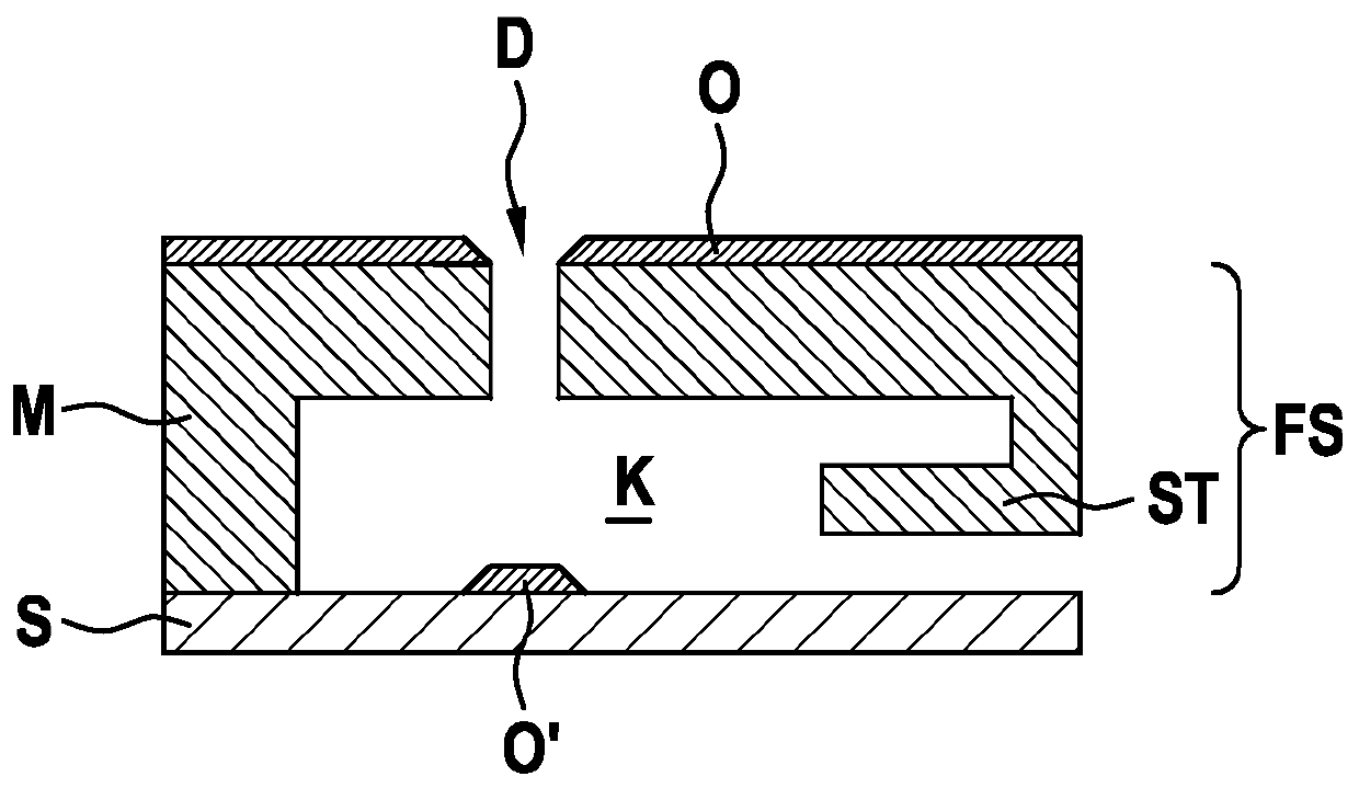
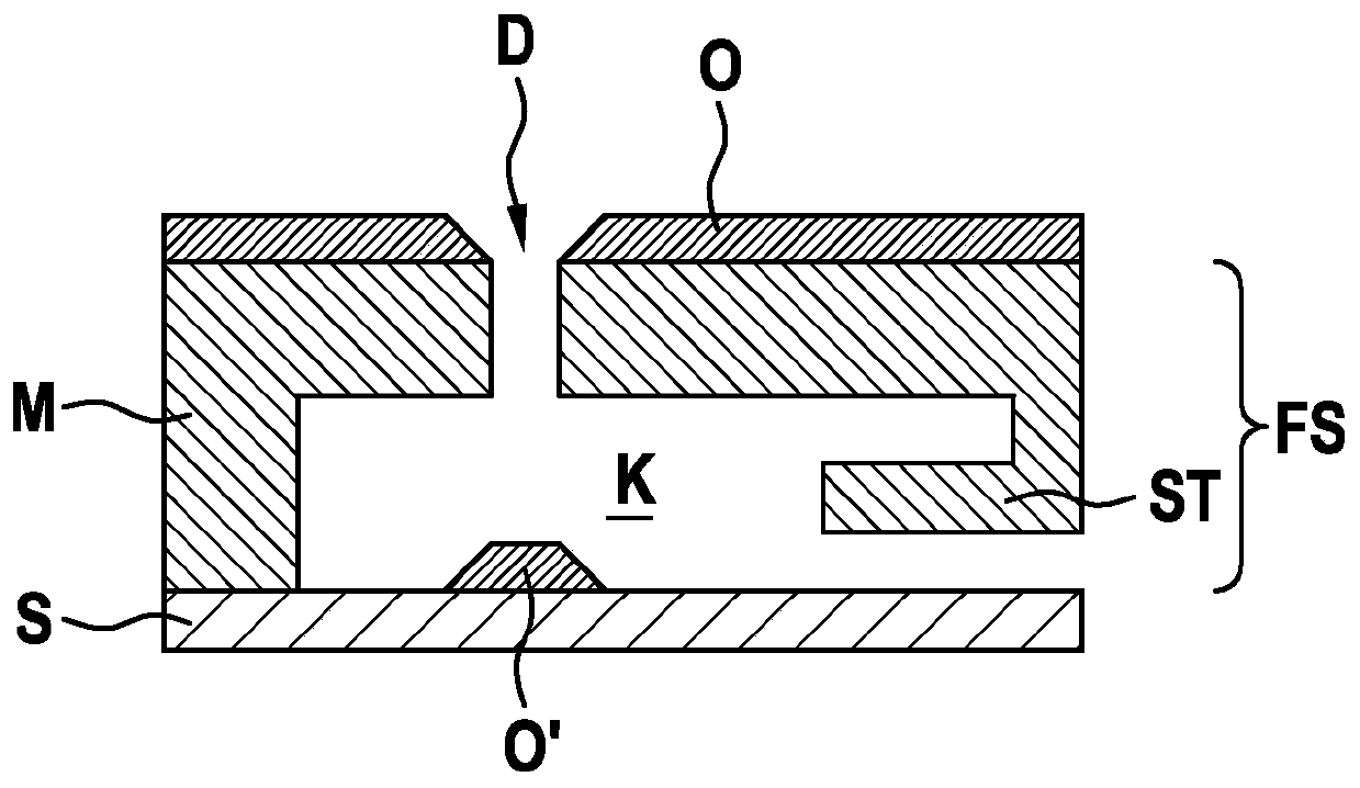
[0058] 1a)-g) are schematic partial cross-sectional views for explaining the manufacturing method for the MEMS structure according to the first embodiment of the present invention.

[0059] According to Figures 1a)-g), a substrate S is provided on which a micromechanical functional layer assembly FS is applied, which functional layer assembly has one or more functional layers. The substrate S is, for example, a silicon wafer substrate, and the functional layer component FS includes, for example, one or more functional layers composed of polysilicon, oxide, nitride, metal, and the like. The functional layer component FS has a cavity K which has a smaller lateral extension than the functional layer component FS. According to FIG. 1a), the through opening is exposed toward the outside of the functional layer assembly FS.

[0060] The cavity K is spanned by a membrane M for absolut...


PUM


Abstract

The invention provides a method for producing a MEMS structure and a corresponding MEMS structure as well as a MEMS component. The method has the following steps: providing a substrate (S) with a micromechanical functional layer arrangement (FS) applied thereon and having one or more functional layers, the functional layer arrangement (FS) having a cavity (K) which is opened via a through opening(D; D'), which has a smaller lateral extent than the functional layer arrangement (FS), is exposed towards an outside of the functional layer arrangement (FS); and depositing a sealing layer (O, O') over the outside of the functional layer arrangement (FS) and the through opening (D; D') by means of an HDP method in such a way that a first region (O) of the sealing layer (O, O') the outside of thefunctional layer arrangement (FS) grows and a second area (O') of the sealing layer (O, O') grows in columnar form from within the cavern (K) below the through opening (D; D'), the second area (O') of the sealing layer (O, O') forms a sealing area (VBO) in the through opening (D; D').

Description

Technical field [0001] The invention relates to a method for manufacturing a MEMS structure and a corresponding MEMS structure. Background technique [0002] Although arbitrary micromechanical components (mikromechanische Bauelemente, abbreviated as MEMS) can also be used, the invention and the problems based on the invention are explained based on the MEMS absolute pressure sensor device. [0003] Many MEMS components require a confined air pressure enclosed in a cavity (Kaverne) to operate, especially in vacuum or at least at a pressure far below 100 Torr. As an example of this, there may be mentioned, for example, a system that performs resonance, such as a rotational speed sensor device, an oscillator that works as a time reference, or a MEMS absolute pressure sensor device. [0004] Figures 5a)-c) are schematic cross-sectional views for explaining an exemplary manufacturing method of a MEMS structure in the form of an absolute pressure sensor device and its mode of action. [00...

Claims


Application Information

Patent Timeline
IPC IPC(8): B81C1/00B81B7/02G01L9/00G01L19/00
CPCB81B7/02B81B2201/0264B81C1/00015B81C1/00349G01L9/00G01L19/00B81C1/00158B81C1/0038B81C2201/0119B81C2201/0122B81C2201/0181G01L9/0042
Inventor J·莱茵穆特T·弗里德里希
Owner ROBERT BOSCH GMBH
Why Eureka
Try Eureka