

Grid type sewage treatment apparatus
A sewage treatment device and grid technology, which is applied in water/sewage treatment, water/sewage treatment equipment, water/sludge/sewage treatment, etc. Clogging and other problems, to achieve the effect of improving filtration treatment, reducing labor costs, and avoiding clogging
- Summary
- Abstract
- Description
- Claims
- Application Information
AI Technical Summary
Problems solved by technology
Method used
Image

Examples
Embodiment 1
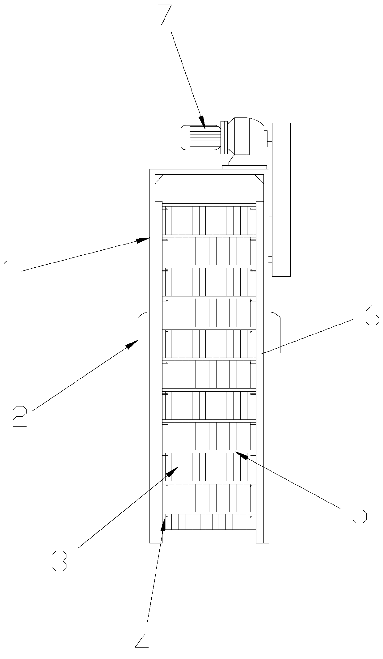
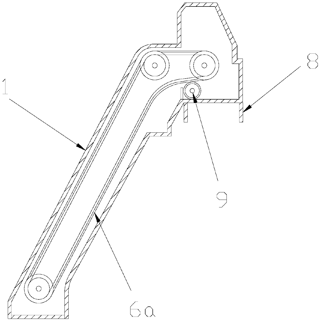
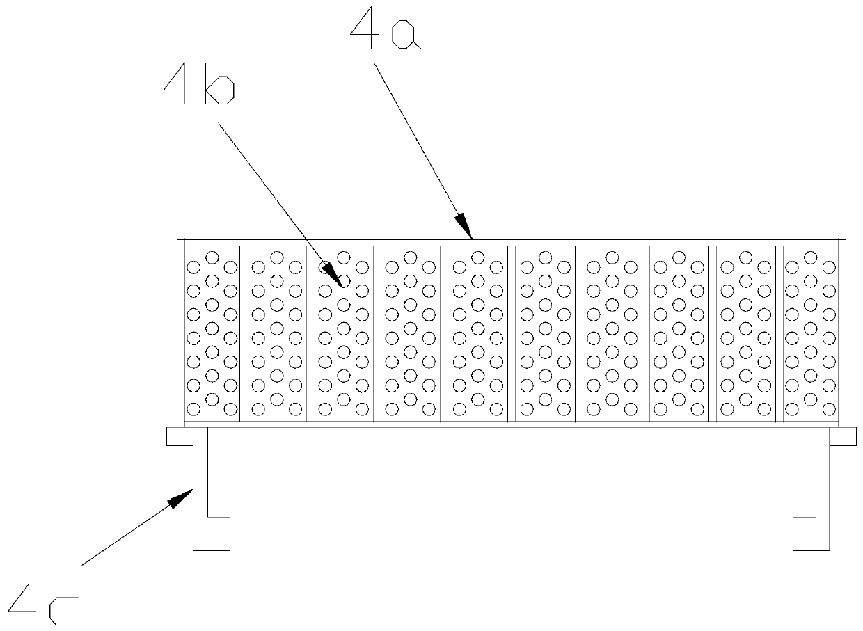
[0028] see Figure 1-Figure 5 , the present invention provides a grid-type sewage treatment device, the structure of which includes a grid sewage cleaning machine 1, a bracket 2, a grid bar 3, a secondary decontamination mechanism 4, rake teeth 5, a traction chain 6, a driving device 7, The slag discharge conduit 8, the rejecting mechanism 9, the grid sewage cleaning machine 1 is provided with a bracket 2 on the surface, the grid sewage cleaning machine 1 and the bracket 2 are welded by electric welding, the grid sewage cleaning machine 1 A driving device 7 is installed on the top, and a traction chain 6 is arranged on the inner side of the grid sewage cleaning machine 1, and the described grid sewage cleaning machine 1 and the traction chain 6 are movably connected, and the traction chain 6 There is a grid bar 3 on the inner side, the traction chain 6 and the grid bar 3 are tenon-connected, and the rake teeth 5 are arranged on the front surface of the grid bar 3, and the grid...
Embodiment 2
[0036] see Figure 1-Figure 7 , the present invention provides a grid-type sewage treatment device, the rejecting mechanism 9 is composed of a drum 9a, a rotating shaft 9b, a rejecting bar 9c, a brush 9d, and a linkage gear 9e, and the left and right ends of the drum 9a are A rotating shaft 9b is provided, the cylinder 9a is fixedly connected to the rotating shaft 9b, the surface of the cylinder 9a is provided with a rejecting strip 9c, the cylinder 9a is glued to the rejecting strip 9c, and the surface of the rejecting strip 9c is provided with There is a brush 9d, the rejecting bar 9c is connected with the brush 9d, the surface of the rotating shaft 9b is provided with a linkage gear 9e, and the rotation shaft 9b is fixedly connected with the linkage gear 9e.
[0037] The surface of the rotating shaft 9b is provided with a positioning frame 9b1, the rotating shaft 9b and the positioning frame 9b1 are connected by a bearing ring 9b2, the top of the positioning frame 9b1 is pr...
PUM
 Abstract
Description
Claims
Application Information