
Concrete vibrating device for cast-in-place ballastless track bed construction

The technology of a vibrating device and a ballast bed is applied in the field of vibrating devices for railway engineering construction, which can solve the problems of low construction accuracy and increased construction cost, and achieve the effects of good vibration reduction effect, improved construction accuracy and convenient operation.

Pending Publication Date: 2020-08-07
中铁十七局集团第五工程有限公司 +1
View PDF0 Cites 3 Cited by
  • Summary
  • Abstract
  • Description
  • Claims
  • Application Information

AI Technical Summary

Problems solved by technology

[0004] The present invention provides a concrete vibrating device for cast-in-place ballastless track bed construction in order to solve the problems of low construction accuracy and increased construction cost in the application of existing workers standing on tool rails for vibrating

Method used


Image

  • Concrete vibrating device for cast-in-place ballastless track bed construction

Examples


Embodiment Construction

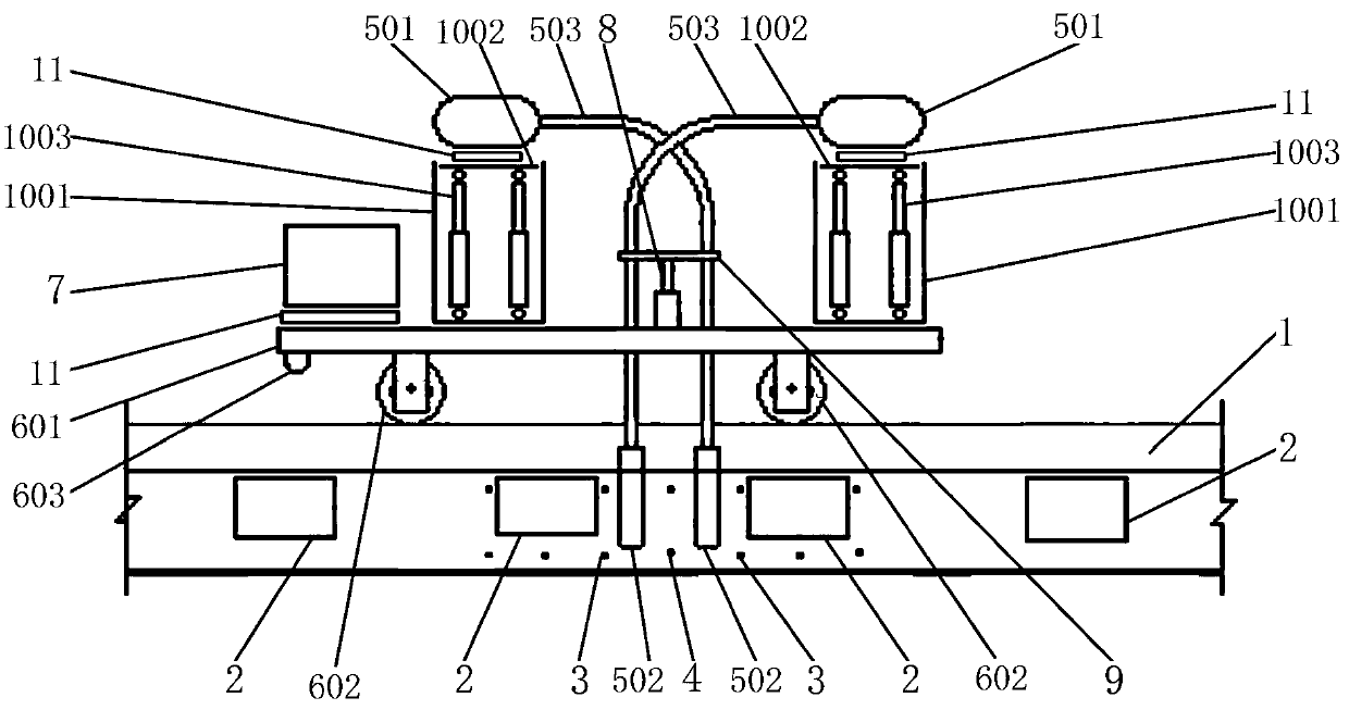
[0025] A concrete vibrating device for the construction of cast-in-place ballastless beds includes two tool rails 1 and several rows of sleepers 2 distributed left and right; two adjacent rows of sleepers 2 are provided with two rows of front-to-rear and laterally distributed guards. There is a row of structural steel bars 4 placed in the same direction as the two rows of anti-cracking structure bars 3, and there are operating gaps between the two rows of anti-cracking structure bars 3 and the structural steel bars 4; It includes eight plug-in vibrators and an electric flat car that runs on two tool rails 1 in the left-right direction; the plug-in vibrator includes a vibration motor 501, a vibrating rod 502, and a soft vehicle connected between the two. Axle tube 503; The electric flat car includes a frame 601, a stepping motor and a number of rail wheels 602, and its stepping distance is equal to the distance between two adjacent rows of sleepers 2;

[0026] The upper surface of...


PUM


Abstract

The invention particularly relates to a concrete vibrating device for cast-in-place ballastless track bed construction, and solves the problems of low construction precision and increased constructioncost in application of an existing vibrating mode that an operator stands on a tool rail. The concrete vibrating device for cast-in-place ballastless track bed construction is characterized in that agenerator, a PLC, two vibration reduction boxes and a plurality of electric push rods are arranged on the upper surface of a vehicle frame; the top end parts of the electric push rods are jointly andfixedly connected with a lifting bracket; eight vibration motors are placed on the upper surfaces of the two vibration reduction boxes, and eight flexible shaft tubes are fixedly connected to the lifting bracket; and eight vibration rods are arranged in two operation gaps, and the PLC is connected with a stepping motor, the electric push rods and the eight vibration motors. The purpose that an operator operates vibrating operation outside the line is achieved, the vibration reduction effect is good, automatic stepping is achieved, operation is convenient and fast, the construction precision and the construction efficiency are effectively improved, and the device is suitable for vibrating operation of the cast-in-place ballast bed.

Description

Technical field [0001] The invention relates to a vibrating device for railway engineering construction, in particular to a concrete vibrating device for construction of cast-in-place ballastless beds. Background technique [0002] Since the beginning of this century, my country has accelerated the pace of high-speed railway construction, and the use of CRTSⅠ double block and elastic support block ballastless tracks (referred to as cast-in-place ballastless beds) has increased. At present, most domestic constructions use conventional equipment such as gantry cranes, concrete tankers, and concrete pumps to pour the concrete, and the operators stand on the tool rails and hold the vibrating tools to perform vibrating operations. [0003] However, practice shows that the existing methods of operators standing on the tool rail and vibrating have the following problems in application: First, it will affect the construction accuracy. When vibrating, the operators need to stand on the tool...

Claims


Application Information

Patent Timeline
IPC IPC(8): E01B29/00
CPCE01B29/00
Inventor 徐彦军王树成汪梨园康艳军张治荣冯爱陈晋魏强高飞孙志兵
Owner 中铁十七局集团第五工程有限公司
Learn More