
Sludge collecting vehicle with spiral separation mechanism

A technology of spiral separation and collection vehicle, which is used in sludge treatment, water/sludge/sewage treatment, road cleaning, etc., and can solve problems such as large manpower and material resources, inability to discharge accumulated water, and clogging of sewers.

Active Publication Date: 2020-08-07
广东润威建设工程有限公司
View PDF10 Cites 1 Cited by
  • Summary
  • Abstract
  • Description
  • Claims
  • Application Information

AI Technical Summary

Problems solved by technology

[0002] During the rainy season in the south, floods are prone to occur after a long period of heavy rain. The floods will bring the silt in the river to the city with the flood. If it is not handled in time or handled properly, the sewer may be blocked, resulting in the inability to drain away the accumulated water and increasing the time for post-disaster reconstruction; while the existing method of removing silt is to use a broom to shovel away the silt, which requires a lot of manpower and material resources. And it takes a lot of time to clean it up, and it is impossible to improve the removal efficiency of street silt; and when the street sewer is blocked, the accumulated water cannot be discharged, and it is easy for people to step on the water to clean up the silt when the accumulated water is deep. The use of pumps to drain the water before cleaning the sludge can start, resulting in inefficiency

Method used


Image

  • Sludge collecting vehicle with spiral separation mechanism
  • Sludge collecting vehicle with spiral separation mechanism
  • Sludge collecting vehicle with spiral separation mechanism

Examples


Embodiment Construction

[0027] Below, the present invention will be further described in conjunction with the accompanying drawings and specific implementation methods. It should be noted that, under the premise of not conflicting, the various embodiments described below or the technical features can be combined arbitrarily to form new embodiments. .

[0028] The utility model relates to a silt collecting vehicle with a spiral separation mechanism, which can quickly remove the silt on the street when the street water cannot be discharged or the street water is drained away.

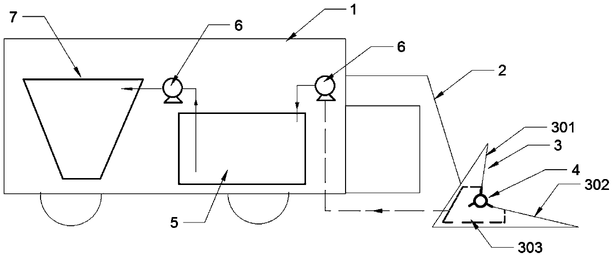
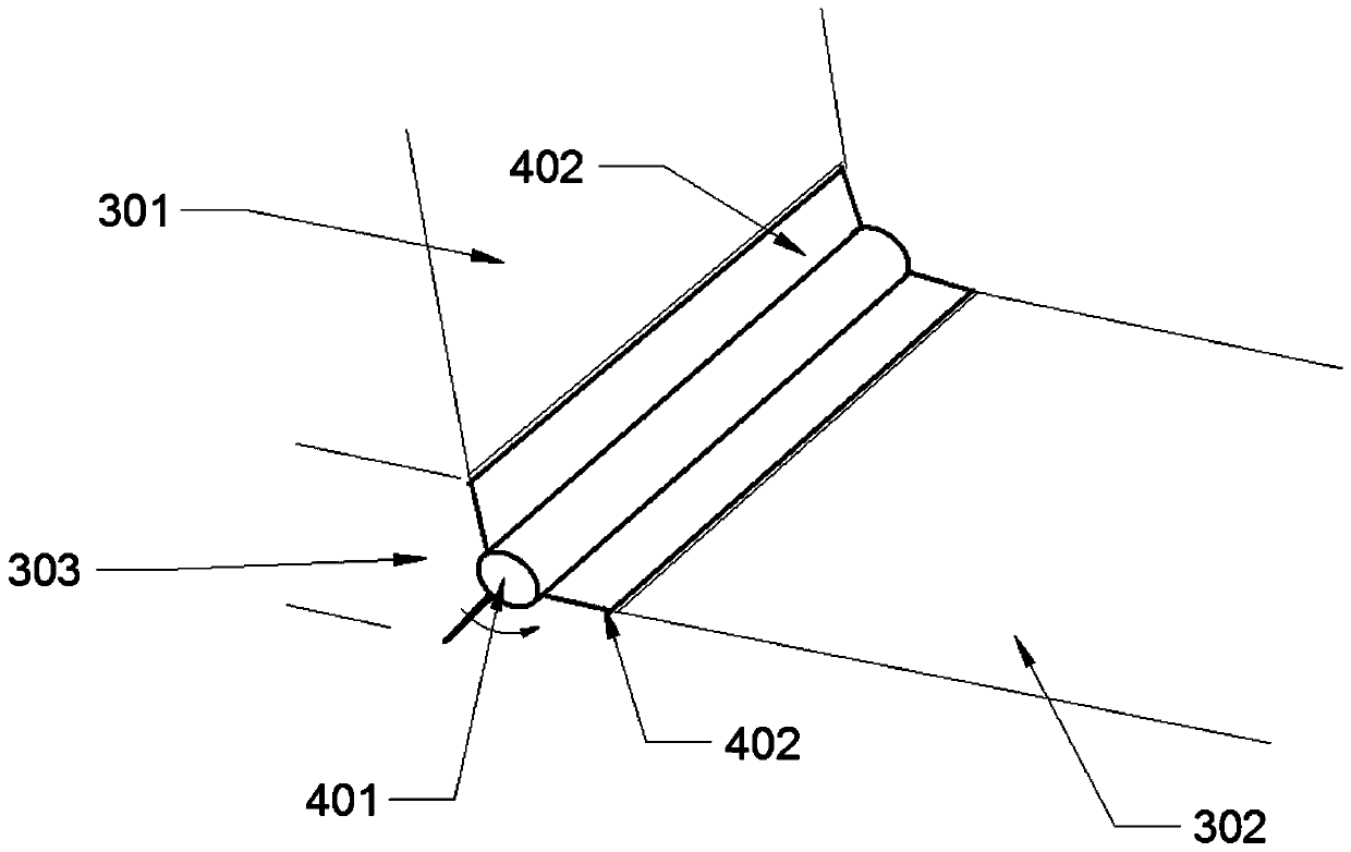
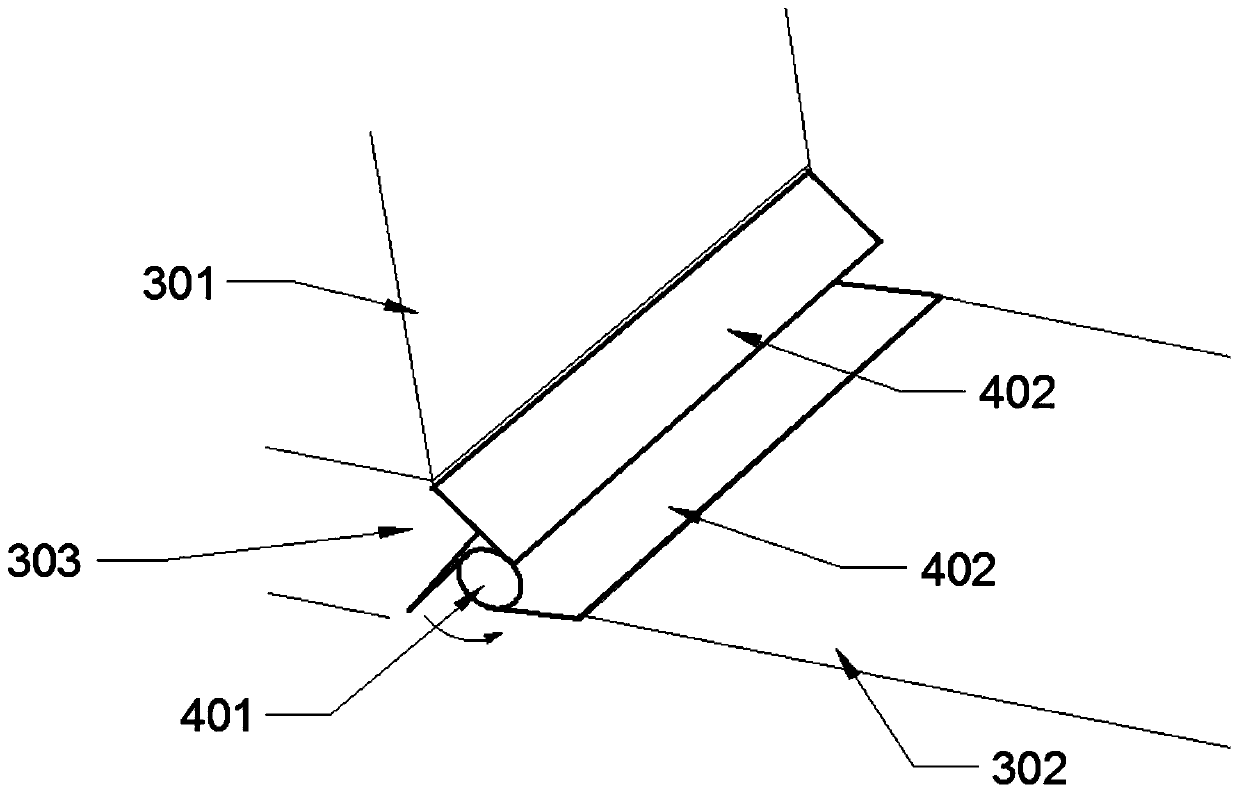
[0029] Such as figure 1 As shown, the silt collection vehicle includes a car body 1, the car body 1 is equipped with a mechanical arm 2, and the end of the mechanical arm 2 is provided with a mud collection mechanism, which can be controlled by controlling the mechanical arm 2. Adjusting the angle of the mud-collecting mechanism makes the mud-collecting mechanism more closely attached to the bottom surface, so as to facilitate ...


PUM


Abstract

The invention discloses a sludge collection vehicle with a spiral separation mechanism. The sludge collection vehicle comprises a vehicle body, a sludge collecting mechanism which is arranged on the vehicle body, is close to the ground and is used for collecting sludge on the ground when the vehicle body runs; a stirring pool which is arranged in the vehicle body, the stirring pool is connected with the sludge collecting mechanism through a water inlet pipe provided with a water pump, and the stirring pool is further connected with the sludge-water separating mechanism through a water outlet pipe provided with a water pump; a mud-water separation mechanism, wherein the mechanism is arranged in the vehicle body and comprises an inner wall of a hollow inverted-cone-shaped structure. A feeding hole communicated with the water outlet pipe is formed in the top of the inner wall; the water outlet direction of the feeding hole is tangent to the cross section of the inner wall where the feeding hole is formed; the inner wall is provided with a plurality of meshes, muddy water sprayed out of the feeding port spirally flows downwards along the inner wall, the muddy water is made to move in acentrifugal mode, water in the muddy water is thrown out of the meshes, and sludge left after flood disasters on streets is collected.

Description

technical field [0001] The invention relates to the field of road sludge treatment, in particular to a sludge collection vehicle with a spiral separation mechanism. Background technique [0002] During the rainy season in the south, floods are prone to occur after a long period of heavy rain. The floods will bring the silt in the river to the city with the flood. If it is not handled in time or handled properly, the sewer may be blocked, resulting in the inability to drain away the accumulated water and increasing the time for post-disaster reconstruction; while the existing method of removing silt is to use a broom to shovel away the silt, which requires a lot of manpower and material resources. And it takes a lot of time to clean it up, and it is impossible to improve the removal efficiency of street silt; and when the street sewer is blocked, the accumulated water cannot be discharged, and it is easy for people to step on the water to clean up the silt when the accumulate...

Claims


Application Information

Patent Timeline
IPC IPC(8): E01H1/10C02F11/127
CPCE01H1/106C02F11/127
Inventor 张木金郑妙璇
Owner 广东润威建设工程有限公司
Learn More