Floor drain capable of preventing hair blockage

A floor drain and hair technology, applied in the field of sanitary ware, to achieve the effect of promoting rotation, increasing anti-blocking effect, and increasing efficiency

Pending Publication Date: 2020-08-07
王双炎
View PDF6 Cites 3 Cited by
  • Summary
  • Abstract
  • Description
  • Claims
  • Application Information

AI Technical Summary

Problems solved by technology

[0004] The purpose of the present invention is to solve the disadvantages in the prior art that the porous cover plate cannot effectively block the hair from entering the downpipe and cause the downpipe to be blocked, and proposes a floor drain that prevents hair from clogging

Method used


Image

  • Floor drain capable of preventing hair blockage
  • Floor drain capable of preventing hair blockage

Examples


Embodiment 1

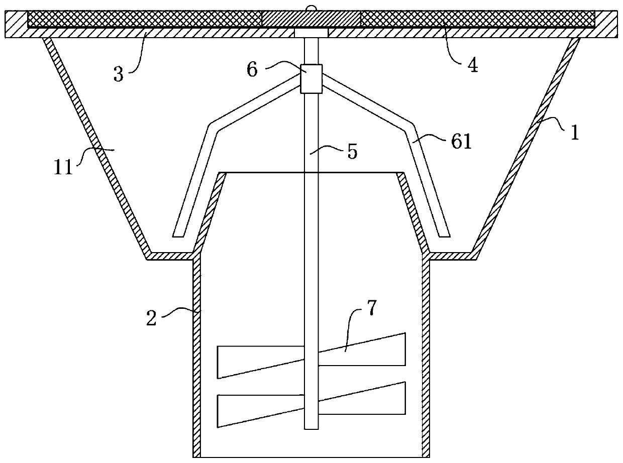
[0022] refer to figure 1 , a floor drain for preventing hair clogging, comprising a conical drain body 1, the conical drain body 1 includes a water leakage chamber 11, a drain pipe 2 is inserted and installed at the lower end of the conical drain body 1, and the upper end of the leak pipe 2 is higher than the water leakage chamber On the inner bottom surface of 11, a support frame 3 is installed on the tapered drain body 1, a filter cover 4 is provided on the upper cover of the support frame 3, a rotating shaft 5 is installed on the center of the supporting frame 3, and a shaft sleeve 6 is installed on the upper end of the rotating shaft 5, A plurality of cleaning rods 61 are symmetrically installed on the shaft sleeve 6, and the lower end of each cleaning rod 61 is located between the upper end outer wall of the drain pipe 2 and the inner wall of the leakage chamber 11, and the lower end of the rotating shaft 5 extends into the drain pipe 2 and is installed with swirl blade 7...

Embodiment 2

[0027] refer to figure 2 , an anti-hair clogging floor drain, which is basically consistent with Embodiment 1, the difference is that:

[0028] A plurality of first movable rods 62 are mounted on the shaft sleeve 6 for symmetrical rotation, and the lower end of each first movable rod 62 is rotatably mounted with a second movable rod 63;

[0029] The rotating shaft 5 rotates and drives the axle sleeve 6 to rotate, and the axle sleeve 6 rotates so that the first movable lever 62 and the second movable lever 63 rotate, that is, the first movable lever 62 and the second movable lever 63 rotate to collect the hair, and when cleaning, the rotation lifts the Lifting the first movable rod 62 and the second movable rod 63 enables the hair to be easily cleaned out of the water leakage chamber 11, increasing the convenience of use.

[0030] In this embodiment, the first movable rod 62 and the second movable rod 63 are driven by the rotation of the shaft sleeve 6 to rotate and wrap arou...


PUM


Abstract

The invention discloses a floor drain capable of preventing hair blockage. The floor drain comprises a conical drain body, wherein the conical drain body comprises a water leakage cavity; a drain pipeis inserted into the lower end of the conical drain body; the upper end of the drain pipe is higher than the inner bottom surface of the water leakage cavity; a support frame is mounted on the conical drain body; a filter cover covers the support frame; a rotating shaft is rotationally mounted in the center of the support frame; a shaft sleeve is mounted at the upper end of the rotating shaft; aplurality of cleaning rods are symmetrically mounted on the shaft sleeve; and the lower end of each cleaning rod is positioned between the outer wall of the upper end of the drain pipe and the inner side wall of the water leakage cavity. The cleaning rods are driven by water flow and swirl vanes to rotate to collect hair in the water leakage cavity, the hair is prevented from entering a sewer pipethrough the drain pipe, and the anti-blocking effect is improved; and by means of the design that the upper end of the drain pipe is higher than the bottom surface of the water leakage cavity, an undisturbed vortex is formed in the water leakage cavity, the drainage speed is increased, and the collected hair is conveniently cleaned out of the water leakage cavity by the aid of a first movable rodand a second movable rod.

Description

technical field [0001] The invention relates to the field of sanitary ware, in particular to a hair-blocking-proof floor drain. Background technique [0002] There is usually a floor drain in the bathroom to quickly discharge the sewage in the bathroom, and the sewage in the bathroom is usually mixed with hair that fell during bathing. The hair enters the sewer pipe through the floor drain and easily entangles subsequent impurities to form larger impurities and block the sewer pipe. Therefore, the anti-blocking performance of the floor drain is particularly important. [0003] Existing floor drains usually block larger impurities from entering the downpipe through the porous cover above the floor drain, but hair can still enter the sewer through the porous cover, which has a low degree of blocking for hair. Contents of the invention [0004] The object of the present invention is to solve the disadvantages in the prior art that the porous cover plate cannot effectively bl...

Claims


Application Information

Patent Timeline
Patent Type & Authority Applications(China)
IPC IPC(8): E03F5/04
CPCE03F5/0407
Inventor 李丽萍
Owner 王双炎
Why Eureka
Try Eureka