Self-excited vibrator construction device

A technology of building construction and installation department, which is applied in the field of self-excited vibration building construction devices, which can solve the problems of high labor intensity, poor paste quality, and low paste efficiency, and achieve the effect of uniform percussion force and low labor intensity

Active Publication Date: 2020-08-07
安徽同济水电建安有限公司
View PDF6 Cites 0 Cited by
  • Summary
  • Abstract
  • Description
  • Claims
  • Application Information

AI Technical Summary

Problems solved by technology

[0005] The purpose of the present invention is to solve the problems of high labor intensity, low paste efficiency and poor paste quality by manual pasting of high-altitude and large-size exterior wall bricks, and a self-excited vibration building construction device is proposed.

Method used


Image

  • Self-excited vibrator construction device
  • Self-excited vibrator construction device
  • Self-excited vibrator construction device

Examples


Embodiment 1

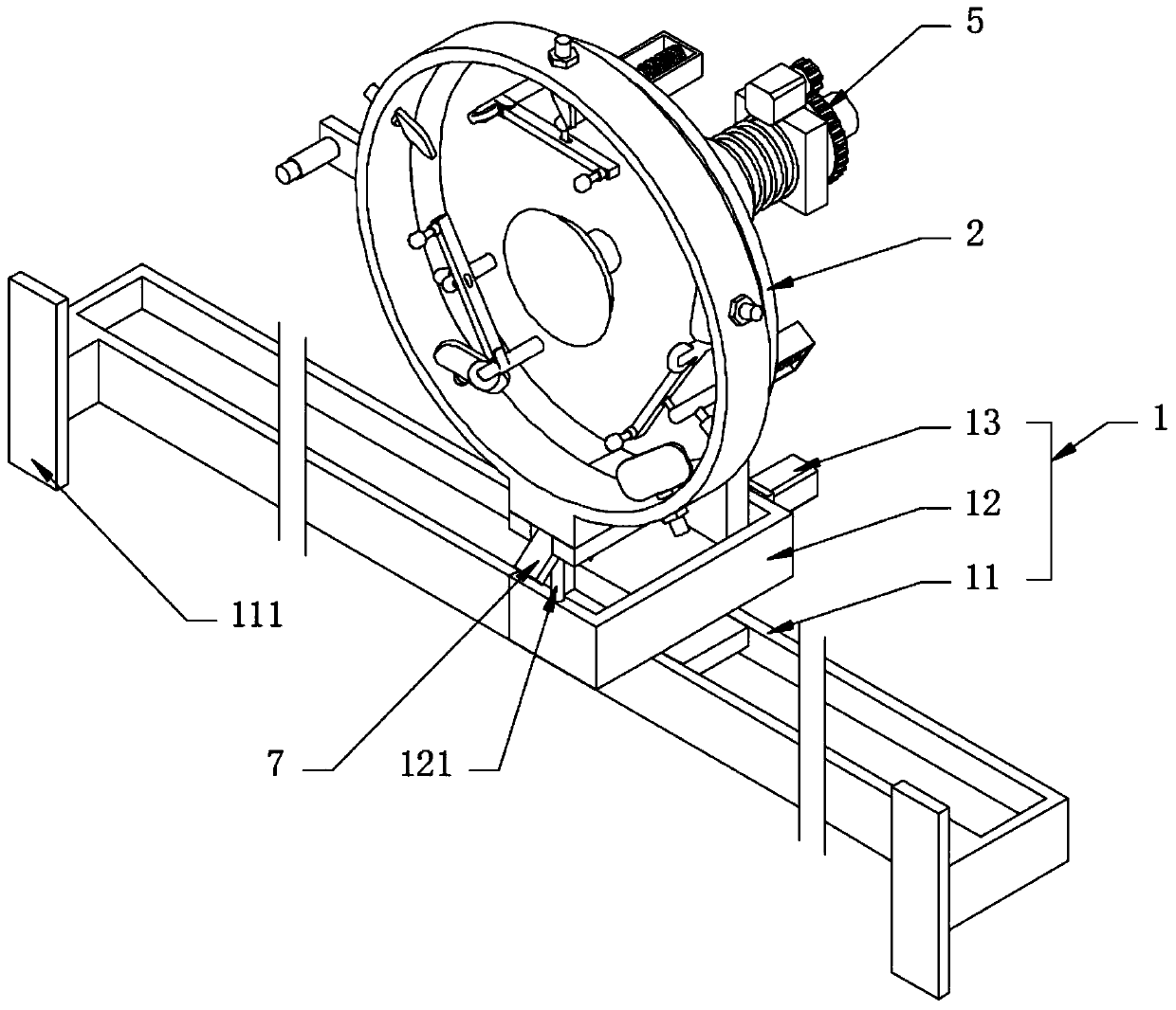
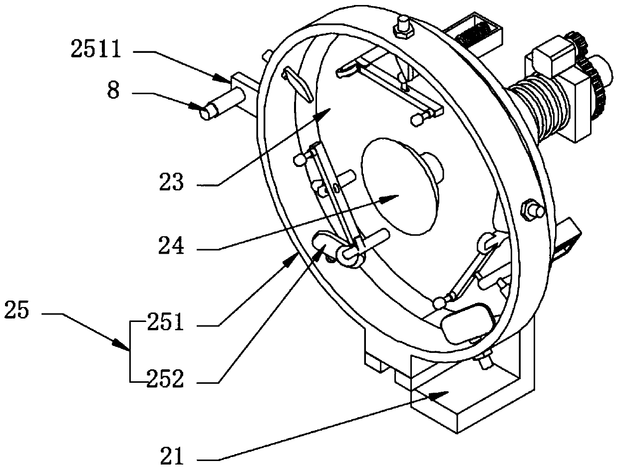
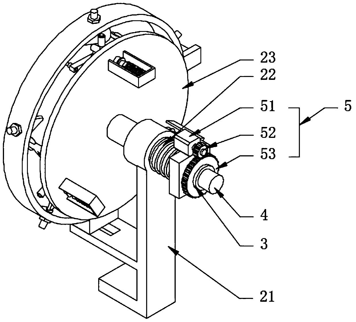
[0034] see Figure 1-4, a self-excited vibration building construction device, including a supporting sliding composite beam 1, a vibration mounting part 2 and a driving combination 5; the supporting sliding composite beam 1 includes a supporting beam 11, a bearing plate 12 slidingly fitted on the supporting beam 11 in the longitudinal direction and The electric telescopic rod 13 arranged on one end of the bearing plate 12, the front side of the support beam 11 and the two ends are provided with a T-shaped mounting plate 111, the support beam 11 is installed on the high-altitude outer wall through the T-shaped mounting plate 111, and the support beam 11 is Horizontal distribution; the vibration installation part 2 includes a support plate 21, a guide sleeve 22, a vibration turntable group 23, a suction cup 24 and a bump positioning ring 25, and the top of the support plate 21 is elastically slid with the guide sleeve 22; the bottom of the support plate 21 and the bearing plate ...

Embodiment 2

[0036] see Figure 5 The difference from Embodiment 1 is that one end of the slope plate 252 is fixedly provided with a screw rod 2521 that is threaded through the annular plate 251, and a locking nut 6 is screwed on the screw rod 2521, and the driving column 234 can be adjusted by adjusting the locking nut 6. Knocking amplitude; on the driving column 234 and on one side of the limit block 2341, an adjusting nut 9 is screwed, and the compression range of the driving spring 235 can be adjusted by rotating the adjusting nut 9, and then the knocking intensity of the driving column 234 can be adjusted.

Embodiment 3

[0038] see Image 6 , and the difference from Embodiment 1 is that one side of the support plate 21 and the lower part of the annular plate 251 are fixedly provided with a supporting plate 211, and one end of the supporting plate 211 is provided with a limit gap 2111, and the angle plate 7 is rotatably connected in the limit gap 2111 , the support plate 12 is fixedly provided with the support lever 121 used in conjunction with the corner plate 7, that is to say, when the outer wall panel and the suction cup 24 need to be docked, firstly the entire support plate 21 is under the control of the electric telescopic rod 13 Place it at the rear, at this time, support the lever 121 to move one side plate of the angle plate 7 to be located at the front side of the ring plate 251, at this time, just place the outer wall panel on the angle plate 7, and then slide the connecting shaft 4 to make the suction cup 24 and absorb and position the exterior wall panels, thereby facilitating the ...


PUM


Abstract

The invention discloses a self-excited vibrator construction device which comprises a supporting and sliding combined beam, a vibrator installing part and a driving assembly. The vibrator installing part comprises a supporting plate, a guide sleeve, a vibrator rotating disc set, a suction cup and bump positioning rings, wherein the guide sleeve, the vibrator rotating disc set, the suction cup andthe bump positioning rings are in elastic sliding fit with the top of the supporting plate. In the self-excited vibrator construction device, the supporting and sliding combined beam and the vibratorinstalling part are arranged, the vibrator installing part is used for carrying an external wall brick, and the vibrator installing part can transversely and longitudinally slide on the supporting andsliding combined beam, so that the butt joint of the external wall brick and an internal wall surface is realized; the vibrator installing part is provided with the vibrator rotating disc set and thebump positioning rings, the vibrator rotating disc set comprises a positioning disc, positioning columns with one ends connected with wheels, L-shaped hitting rods, driving columns and driving springs, slope plates are arranged on the driving columns and the bump positioning rings in cooperation, the hitting rods can form a clockwise hitting trajectory on the surface of an external wall board, the hitting force borne by the external wall board is even, and labor intensity is low.

Description

technical field [0001] The invention relates to the technical field of construction engineering, in particular to a self-excited vibration construction device. Background technique [0002] In the construction of construction projects, in order to improve the appearance of the building, the outer wall bricks are usually pasted on the outer walls. The size and specifications of the outer wall bricks are different. It is difficult to manually paste the external wall tiles. [0003] At present, when pasting wall tiles at high altitude, it is necessary to manually stick and tap them one by one. Therefore, in the process of pasting, the hand-held alignment and tapping are labor-intensive, and the tapping force is uneven, and it is easy to appear between the wall tiles and the adhesive. Empty pockets exist, resulting in an insecure fit. [0004] Therefore, the present invention provides a self-excited vibration building construction device. Contents of the invention [0005] ...

Claims


Application Information

Patent Timeline
Patent Type & Authority Applications(China)
IPC IPC(8): E04F21/18
CPCE04F21/18E04F21/1894
Inventor 朱凯凯
Owner 安徽同济水电建安有限公司
Why Eureka
Try Eureka