Step-back hole mold

A mould, stepped technology, applied in the direction of formwork/formwork/work frame, connectors of formwork/formwork/work frame, construction components on site, etc., can solve the problem of poor protection effect, easy leakage of water, Poor limiting effect and other problems, to achieve the effect of improving compactness, not easy to run out of pulp, and accurate size

Pending Publication Date: 2020-08-07
CHINA CONSTR EIGHT ENG DIV CORP LTD
View PDF0 Cites 1 Cited by
  • Summary
  • Abstract
  • Description
  • Claims
  • Application Information

AI Technical Summary

Problems solved by technology

[0003] In order to overcome the defects existing in the existing technology, a step-down hole mold is now provided to solve the problems of poor limiting effect, poor protection effect and easy water leakage of the traditional aluminum mold material transfer mouth mold.

Method used


Image

  • Step-back hole mold
  • Step-back hole mold
  • Step-back hole mold

Examples


Embodiment Construction

[0020] Embodiments of the present invention are described below through specific examples, and those skilled in the art can easily understand other advantages and effects of the present invention from the content disclosed in this specification. The present invention can also be implemented or applied through other different specific implementation modes, and various modifications or changes can be made to the details in this specification based on different viewpoints and applications without departing from the spirit of the present invention.

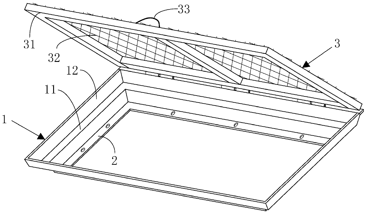
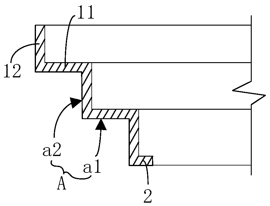
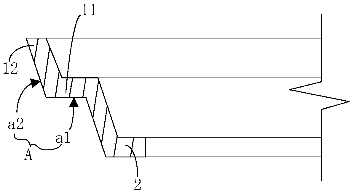
[0021] figure 1 It is a structural schematic diagram of a step-down hole mold according to an embodiment of the present invention, figure 2 It is a cross-sectional view of the hole frame cover of the embodiment of the present invention, image 3 It is a cross-sectional view of an opening frame cover in another implementation manner of the embodiment of the present invention.

[0022] refer to Figure 1 to Figure 3 As shown, the pr...


PUM


Abstract

The invention provides a step-back hole mold which comprises a hole frame sleeve, a reinforcing flange and a cover plate, wherein a plurality of inverted steps are formed on the outer wall of the holeframe sleeve and towards the outer side of the hole frame sleeve from bottom to top, the reinforcing flange is used for installing a hole formwork, the edges of a lower opening of the hole frame sleeve extend towards the inner side of the hole frame sleeve to form the reinforcing flange, and the reinforcing flange is arranged on the edges of the lower opening by a circle in the circumferential direction; and the cover plate is used for shielding an upper edge of the hole frame sleeve, and the cover plate can be foldably installed at the top of the hole frame sleeve. The step-back hole mold solves the problems of poor positioning effect, poor protection effect and easy water leakage of a traditional aluminum mold material transferring port mold.

Description

technical field [0001] The invention relates to the technical field of building construction, in particular to a step-down hole mold. Background technique [0002] With the rapid development of my country's housing construction industry in recent years and the influence of industry innovation drive, various industry tools and facilities are developing in the direction of high efficiency, convenience and reliability, and the finalized aluminum mold material transfer port mold is one of them. At present, the mold structure of the aluminum mold material transfer port is various. Generally speaking, openings are left on the aluminum mold template, and the steel box made of steel plate or angle steel is placed together. Slurry is formed during the concrete pouring process; secondly, the top of the steel box is open, which poses the risk of the upper part of the person falling and debris scattered, and the safety protection effect is poor; The cross-section is relatively simple, ...

Claims


Application Information

Patent Timeline
IPC IPC(8): E04G15/06E04G17/00E04G21/32
CPCE04G15/063E04G17/00E04G21/3233
Inventor 李洪杰孙红岩邱忠会滕飞
Owner CHINA CONSTR EIGHT ENG DIV CORP LTD
Why Eureka
Try Eureka