
Outdoor security tent cage for both military and civilian use, which can block moisture and change gaps, and a method for displaying products in a museum

A tent cage and safety technology, applied in tents/canopies, building types, buildings, etc., can solve the problems of not being able to isolate moisture, not having many uses, and being unable to change gaps, etc., to achieve the effect of changing gaps and isolating moisture

Active Publication Date: 2021-07-23
山东茂华塑料有限公司 +1
View PDF8 Cites 0 Cited by
  • Summary
  • Abstract
  • Description
  • Claims
  • Application Information

AI Technical Summary

Problems solved by technology

[0003] 1. A thin layer cannot prevent wild animals;
[0004] 2. Not many uses;
[0005] 3. Can not be isolated from moisture;
[0006] 4. Unable to change the gap

Method used


Image

  • Outdoor security tent cage for both military and civilian use, which can block moisture and change gaps, and a method for displaying products in a museum
  • Outdoor security tent cage for both military and civilian use, which can block moisture and change gaps, and a method for displaying products in a museum
  • Outdoor security tent cage for both military and civilian use, which can block moisture and change gaps, and a method for displaying products in a museum

Examples


Embodiment 1

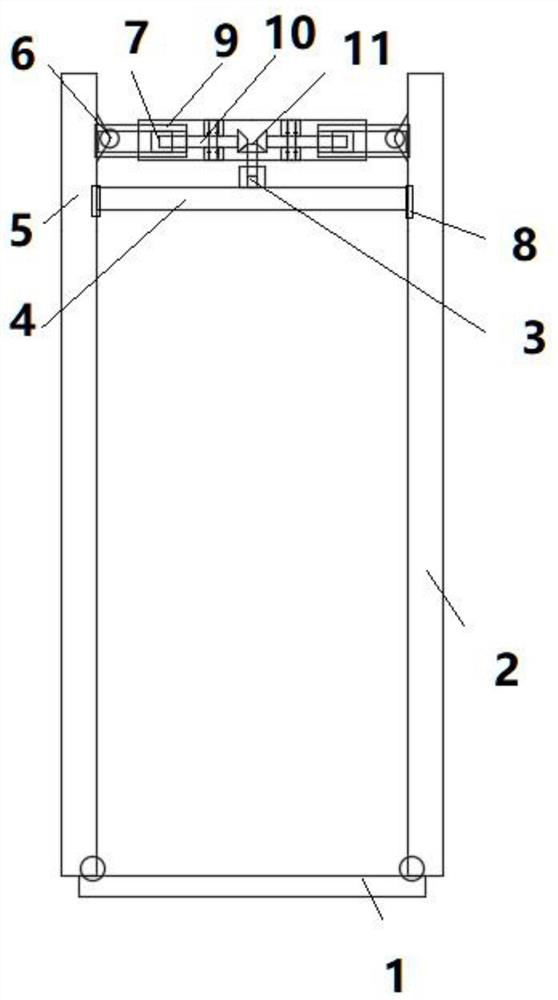
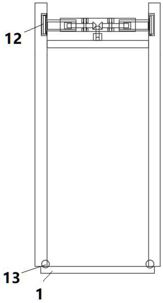
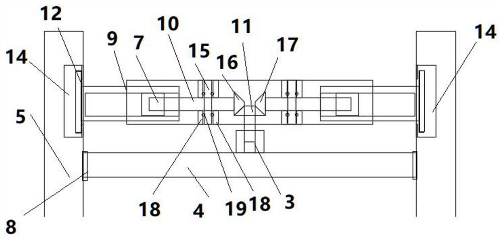
[0069] Example 1: Combining figure 1 with figure 2 The anti-bear outdoor safety tent cage that can be separated from moisture and change gaps is characterized in that it includes a bottom wall 1, and the bottom wall is hinged with more than one push-pull wall through the hinge position 13, and the push-pull wall is connected with the horizontal top wall structure 4 through a spring. , the motor 3 is fixed on the horizontal top wall structure 4, the motor 3 is a forward and reverse motor, the power output shaft of the motor includes a driving bevel gear 11, and the driving bevel gear 11 meshes with the horizontal bevel gear, and the horizontal bevel gear is rotatably installed on a fixed In the sleeve 43, the horizontal bevel gear includes a horizontal shaft 10, and the end of the horizontal shaft 10 includes a threaded block. The threaded block is located in the threaded hole 7 of the threaded sleeve, and the threaded hole of the threaded sleeve is located in the threaded sle...

Embodiment 2

[0072] Embodiment 2: As a further improved solution or a side-by-side solution or an optional independent solution, the fixed sleeve 43 includes two sets of clamping gaps 44, each clamping gap 44 includes two sets of clamping structures 18 up and down, and the clamping structures 18 Containing protrusions, the horizontal shaft 10 includes a clamped structure 15 , and the clamped structure 15 includes a groove 42 , and the groove 42 fits the protrusion to rotatably install multiple horizontal shafts 10 in the fixed sleeve 43 . The substantive technical effect played by the technical solution here and its realization process are as follows: Figure 12 , Figure 13 ; Provide a specific transmission and matching structure, which is convenient to realize the action while rotating.

Embodiment 3

[0073] Embodiment 3: As a further improved solution or a side-by-side solution or an optional independent solution, the fixed sleeve 43 is fixed on the horizontal top wall structure 4 through a fixed shaft.


PUM


Abstract

The invention relates to the field of outdoor devices, in particular to a safety tent cage for both military and civilian use outdoors that can withstand moisture and change gaps, and a method for displaying products in museums. It includes the bottom wall (1), on which more than one push-pull wall is hinged through the hinge position (13), the push-pull wall is connected to the horizontal top wall structure (4) through a spring, and the motor (3) is fixed on the horizontal top wall structure (4 ), the motor (3) is a forward and reverse motor, and the threaded sleeve (9) is hinged to the push-pull wall through the hinge position (6) or the threaded sleeve (9) is sleeved in the receiving recess of the push-pull wall through the inner sleeve plate (12). slot (14). Beneficial effects: it can prevent wild animals; it can be used as a protective device for museums for multiple purposes; it can isolate moisture; it can change gaps.

Description

technical field [0001] The invention relates to the field of outdoor devices, in particular to a safety tent cage for both military and civilian use outdoors that can withstand moisture and change gaps, and a method for displaying products in museums. Background technique [0002] There are following disadvantages in existing tents: [0003] 1. A thin layer cannot prevent wild animals; [0004] 2. Not many uses; [0005] 3. Can not be isolated from moisture; [0006] 4. The gap cannot be changed. Contents of the invention [0007] Purpose of the invention: In order to provide a safety tent cage and method with better effect for both military and civilian use outdoors that can isolate moisture and change gaps, the specific purpose is shown in the multiple substantial technical effects of the specific implementation part. [0008] In order to achieve the above object, the present invention takes the following technical solutions: [0009] Option One: [0010] The bear-...

Claims


Application Information

Patent Timeline
Patent Type & Authority Patents(China)
IPC IPC(8): E04H15/00E04H15/32E04H15/34
CPCE04H15/00E04H15/32E04H15/34
Inventor 梅国强
Owner 山东茂华塑料有限公司
Learn More