
A mine dust removal device

A technology for dust removal devices and mines, which is used in safety devices, dustproofing, mining equipment, etc., can solve the problems of difficult cleaning and one-time use, and achieve the effect of extending the replacement cycle.

Active Publication Date: 2021-10-08
深圳市超立电子有限公司
View PDF9 Cites 0 Cited by
  • Summary
  • Abstract
  • Description
  • Claims
  • Application Information

AI Technical Summary

Problems solved by technology

[0005] In order to solve the above-mentioned technical problems, the present invention provides a mine dust removal device to solve the problem that the existing large-scale dust remover is in the working process, and the internal cylindrical ring-shaped filter cartridge can effectively absorb the suction into the interior through multi-layer pleats. The mixed air can be effectively filtered, and although it can be effectively filtered, it is difficult to clean the folds, so its built-in high-efficiency filter cartridge can only be used for one-time installation, and the mine dust accumulated inside needs to be compared. The high-frequency removal and cleaning of the dust box leads to the problem that it can only work intermittently

Method used

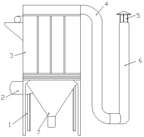

Image

  • A mine dust removal device
  • A mine dust removal device
  • A mine dust removal device

Examples


Embodiment 1

[0030] as attached figure 1 to attach Figure 7 Shown:

[0031] The present invention provides a mine dust removal device, the structure of which includes a support frame 1, an output pipe 2, a dust removal cabinet 3, a dredging pipe 4, a waterproof cover 5, an input bobbin 6, and a cleaning and dispersing device 7. The support frame 1 and The dust removal cabinets 3 are welded together, the cleaning and dispersing device 7 is located inside the bottom of the dust removal cabinet 3, the output pipe 2 is arranged on the left side of the dust removal cabinet 3, and the upper left end of the dredging pipe 4 is welded to the upper right end of the dust removal cabinet 3 , the waterproof cover 5 is located directly above the input tube 6, and the input tube 6 and the dredging tube 4 are socketed together.

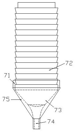
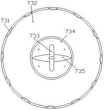
[0032] Said cleaning and filtering device 7 comprises a protruding ring 71, a dust removal filter sleeve 72, a vibration-dividing suction mechanism 73, a suction outer dischar...

Embodiment 2

[0041] as attached Figure 8 Shown:

[0042] The present invention provides a mine dust removal device. The dust removal filter sleeve 72 includes an outer filter ring 721, an inner filter screen 722, a vertical strip 723, a pressing piece 724, a ring bar 725, and a fastener 726. The outer filter ring 721 There is an inner filter 722 inside, the vertical strip 723 is fixedly connected with the fastener 726, the pressing piece 724 is arranged under the fastener 726 and is an integral structure with it, and the ring strip 725 is installed by embedding Inside the outer filter ring 721, the fastener 726 is fastened on the ring bar 725, and its downward pulling force can directly act on the ring bar 725, and the deep fitting connection between the ring bar 725 and the outer filter ring 721 can make It achieves the greatest magnitude of jitter.

[0043] Wherein, the cross-sectional diameter of the ring bar 725 is one-fifteenth of the thickness of the outer filter ring 721, and its...


PUM


Abstract

The invention provides a mine dust removal device, the structure of which includes a support frame, an output pipe, a dust removal cabinet, a dredging pipe, a waterproof cover, an input bobbin, a cleaning and dispersing device, the support frame is welded to the dust removing device, and the cleaning and dispersing device Located inside the bottom of the dust removal case, the output pipe is located on the left side of the dust removal case, and the upper left end of the dredging pipe is welded to the upper right end of the dust removal case. Pressure is applied, so that it can pass through the initial shape of the transformation, and make it continuously switch between the two shapes, so as to indirectly act on the dust filter sleeve, and each layer of dust filter sleeve is in a state of interconnection, which can be simultaneously Perform high-frequency and high-amplitude work on all layers of dust removal filter sleeves, which can effectively cause the attached mineral dust to be passively shot down, and the collected mineral dust released through the dust removal filter sleeves will be collected by negative pressure suction, and The replacement cycle of the dust filter sleeve is greatly extended.

Description

technical field [0001] The invention belongs to the field of ore processing, and more specifically relates to a mine dust removal device. Background technique [0002] When collecting and transporting ore in the mine, due to the large gap in the degree of crushing of the ore during open-pit mining, and the crushing position will appear in a state of local fragmentation with a high degree of fragmentation, which will lead to more mineral dust, in order to protect The working environment of mining construction personnel generally requires the preparation of large-scale dust collectors. [0003] Based on the above description, the inventors found that the existing mine dust removal device mainly has the following deficiencies, such as: [0004] During the working process of the large-scale dust collector, the cylindrical ring-shaped filter cartridge inside can effectively filter the mixed air sucked into the interior through multi-layer pleats. It is difficult to clean, so th...

Claims


Application Information

Patent Timeline
Patent Type & Authority Patents(China)
IPC IPC(8): E21F5/00E21F5/20
CPCE21F5/00E21F5/20
Inventor 朱莉君王佩
Owner 深圳市超立电子有限公司
Learn More