A mid-wave infrared optical system

An infrared optical system and optical system technology, applied in the field of medium-wave infrared optical system, can solve the temperature measurement delay, can not directly reflect the temperature field distribution, can not meet the strong radiation of nuclear reactors, and the temperature field monitoring of the large field of view in the space light environment and measurement issues

Active Publication Date: 2021-09-14
中科精仪吉林省科技有限公司
View PDF9 Cites 0 Cited by
  • Summary
  • Abstract
  • Description
  • Claims
  • Application Information

AI Technical Summary

Problems solved by technology

Traditional contact thermometers such as thermocouples, thermal resistances, etc., need a certain period of time to reach thermal equilibrium due to sufficient heat exchange with the measured substance. There is a phenomenon of temperature measurement delay, and at the same time, it cannot directly reflect a certain measurement The temperature field distribution in the region, so there are certain limitations in the use of temperature field detection in nuclear reactors
[0003] Aiming at the limitations of traditional contact thermometers and the fact that the existing infrared thermometers on the market cannot meet the requirements of strong radiation of nuclear reactors, complex space light environment and large field of view temperature field monitoring and measurement, we invented an infrared thermometer that can meet the needs of nuclear reactors. Instruments or optical systems for temperature field monitoring and measurement play a vital role in improving the safety performance of nuclear reactors

Method used


Image

  • A mid-wave infrared optical system
  • A mid-wave infrared optical system
  • A mid-wave infrared optical system

Examples


Embodiment Construction

[0046] The present invention will be described in further detail below in conjunction with the accompanying drawings and embodiments.

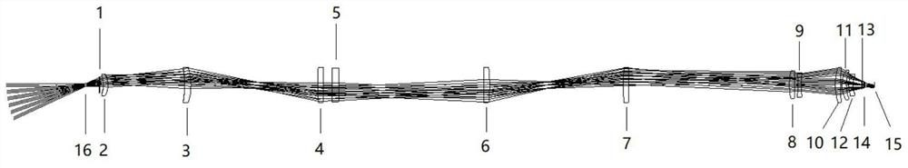
[0047] as attached figure 1 As shown, a medium-wave infrared optical system is composed of an entrance pupil surface, an imaging group, a relay mirror group, a correction mirror group and a detector assembly. The light emitted by the optical system is imaged by the imaging group, and passes through the The secondary mirror couples the image plane of the imaging group to the object plane of the correction group, adjusts the imaging quality through the correction mirror group, and collects imaging information by the detector assembly: except for the detector assembly, there are 12 lenses in total, including 4 10-order aspheric surfaces.

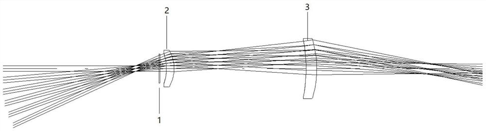
[0048] Such as figure 2 As shown, the imaging group includes a first positive lens 2 and a second positive lens 3 . The above lenses are arranged in sequence, each lens is on the same optical axis, and the ...


PUM

PropertyMeasurementUnit
viewing angleaaaaaaaaaa
lengthaaaaaaaaaa

Abstract

The invention provides a mid-wave infrared optical system, which solves the problem of temperature field measurement in nuclear reactors. The mid-wave infrared optical system includes an anti-pollution protection window, an imaging group, a relay mirror group, a correction mirror group and a detector assembly. The light emitted by the optical system is imaged by the imaging group, the image surface of the imaging group is coupled to the object surface of the correction group through the relay mirror, the imaging quality is adjusted by the correction mirror group, and the imaging information is collected by the detector component: wavelength range The diameter is 3.7um~4.8um, the field of view is 50 degrees, the diameter of the entrance pupil is 6.78mm, the F-number of the system is 2, and the total length of the system is 1770mm. In addition to the detector assembly, a total of 12 lenses are used, of which 10 aspherical surfaces are used on 4 surfaces. The mid-infrared optical system of the present invention has the advantages of easy processing, easy assembly and adjustment, small lens diameter, good imaging quality and the like.

Description

technical field [0001] The invention belongs to the application field of infrared optics, and in particular relates to a mid-wave infrared optical system. Background technique [0002] In nature, when the temperature of an object is higher than absolute zero, due to the existence of its internal thermal motion, it will continuously radiate electromagnetic waves to the surroundings, including infrared rays with a band of 0.75-100um. Infrared temperature field measurement is made using this principle. Temperature is a physical quantity that measures the degree of coldness and heat of an object. It is a very common and important thermal parameter in industrial production. Many production processes require monitoring and monitoring of temperature. Control, especially in nuclear reactors, needs to accurately reflect the temperature field distribution and gauge size in different regions of the nuclear reactor. Traditional contact thermometers such as thermocouples, thermal resist...

Claims


Application Information

Patent Timeline
Patent Type & Authority Patents(China)
IPC IPC(8): G02B13/00G02B13/18G02B13/14G02B1/00
CPCG02B1/00G02B13/00G02B13/14G02B13/18
Inventor 李美萱徐春艳张斯淇张文颖李宏李楠冯悦姝刘小涵
Owner 中科精仪吉林省科技有限公司
Why Eureka
Try Eureka