Pressure intensity control module for pulse diagnosis instrument based on pulse acoustic signal

A technology for controlling modules and acoustic signals, applied in the directions of diagnosis, application, stethoscope, etc., can solve the problems of low convenience and poor intelligence, and achieve the effect of better use diversity

Pending Publication Date: 2020-08-11
OCEAN UNIV OF CHINA
View PDF8 Cites 0 Cited by
  • Summary
  • Abstract
  • Description
  • Claims
  • Application Information

AI Technical Summary

Problems solved by technology

[0004] The purpose of the present invention is to provide a pressure control module for a pulse diagnosis instrument based on the pulse sound signal, to solve the problem that the pressure control module used for the pulse diagnosis instrument proposed in the above-mentioned background technology is mostly manually controlled, that is, the pressure of the air bag in the cuff is high or low. The degree depends on the medical experience of the examiner. When using this kind of pressure module, it is difficult to independently pressurize and release pressure according to the thickness of the patient's wrist and the perceived pulse rate. The convenience of use is low and the degree of intelligence is low. poor problem

Method used


Image

  • Pressure intensity control module for pulse diagnosis instrument based on pulse acoustic signal
  • Pressure intensity control module for pulse diagnosis instrument based on pulse acoustic signal

Examples


Embodiment Construction

[0021] The following will clearly and completely describe the technical solutions in the embodiments of the present invention with reference to the accompanying drawings in the embodiments of the present invention. Obviously, the described embodiments are only some, not all, embodiments of the present invention. Based on the embodiments of the present invention, all other embodiments obtained by persons of ordinary skill in the art without making creative efforts belong to the protection scope of the present invention.

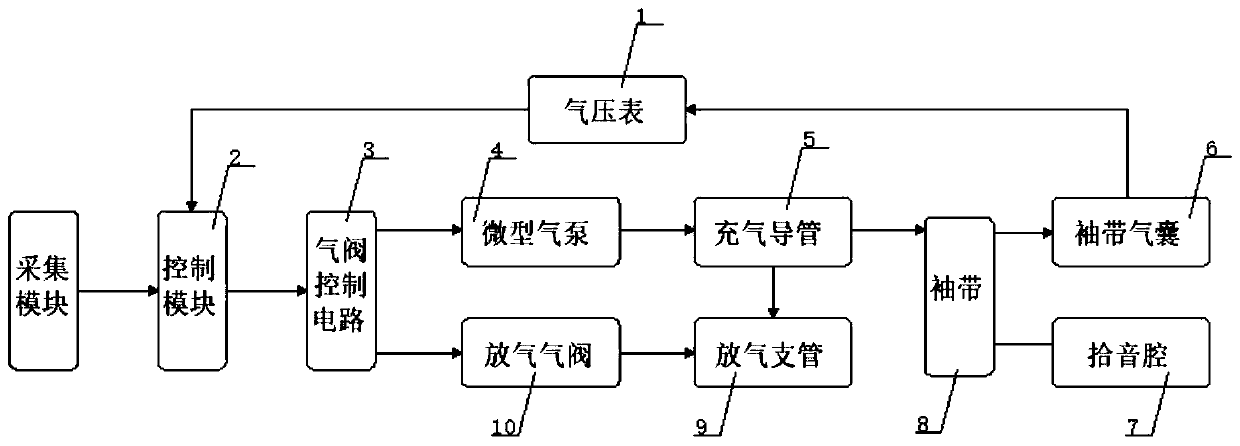
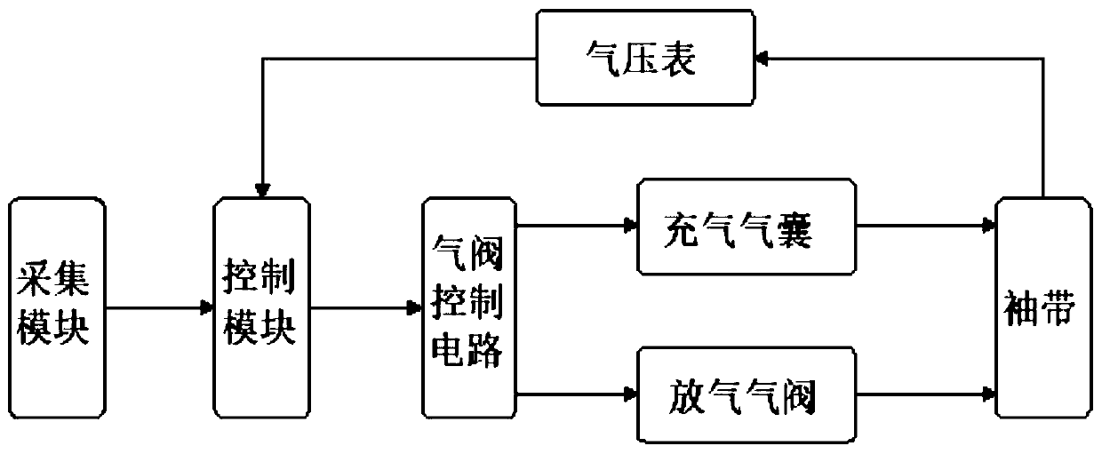
[0022] see Figure 1-2 , the present invention provides a technical scheme of a pressure control module for a pulse diagnosis instrument based on the pulse sound signal:

[0023] A pressure control module for a pulse diagnosis instrument based on a pulse sound signal, comprising a control module 2 and an air valve control circuit 3, the output end of the control module 2 is an air valve control circuit 3, and the output ends of the air valve control circuit 3 ...


PUM


Abstract

The invention discloses a pressure intensity control module for a pulse diagnosis instrument based on a pulse acoustic signal. The pressure intensity control module comprises a control module and a gas valve control circuit, wherein a gas valve control circuit is arranged at the output end of the control module; a deflating gas valve and a miniature gas pump are arranged at the output end of the gas valve control circuit; a deflating branch pipe is arranged at the output end of the deflating gas valve; an inflating duct is arranged at the output end of the miniature gas pump; the deflating branch pipe and a cuff are arranged at the output end of the inflating duct; a cuff air bag is embedded in the inner side of the cuff; a pickup cavity is formed in the outer wall of the front end adjacent to the lower side, of the cuff; the inflating duct and the cuff air bag are arranged at the input end and the output end up and down; a barometer is arranged at the output end of the cuff air bag; and a control module is arranged at the output end of the barometer, and is used for collecting and processing pulse beating information. Through the adoption of the pressure intensity control module disclosed by the invention, the pulse wave form data which is more microcosmic, more complex and richer in more information can be collected under different pressure, so that disease diagnosis is convenient to perform by using the wave form.

Description

technical field [0001] The invention belongs to the related technical field of pulse diagnosis medical equipment, and in particular relates to a pressure control module for a pulse diagnosis instrument based on a pulse sound signal. Background technique [0002] With the progress of society, people pay more and more attention to their own health status, and hope to find a safe, non-invasive and convenient method to diagnose the disease. Therefore, pulse diagnosis methods from traditional Chinese medicine are gradually paid attention to. The doctor applies different pressures on the patient's radial artery with his fingertips, and determines the patient's pulse by relying on the information such as touch, pressure and vibration sensed by the fingertips, and then diagnoses the patient's condition. [0003] The existing pulse diagnosis technology has the following problems: most of the pressure control modules used in the pulse diagnosis device are manually controlled, that is,...

Claims


Application Information

Patent Timeline
Patent Type & Authority Applications(China)
IPC IPC(8): A61B7/04A61B5/02A61B5/0225A61B5/00
CPCA61B7/04A61B5/02A61B5/0225A61B5/4854
Inventor 高大治高德洋王光强王宁
Owner OCEAN UNIV OF CHINA
Why Eureka
Try Eureka