A production system for welding h-shaped steel

A production system, H-shaped steel technology, applied in the direction of welding equipment, auxiliary welding equipment, welding/cutting auxiliary equipment, etc., can solve the problems of complex operation procedures, high labor intensity, low assembly and welding efficiency, etc., to achieve simple operation procedures, reduce The effect of labor intensity and reasonable structural design

Active Publication Date: 2022-01-14
重庆本浩建设工程有限公司
View PDF7 Cites 0 Cited by
  • Summary
  • Abstract
  • Description
  • Claims
  • Application Information

AI Technical Summary

Problems solved by technology

[0004] However, this welding method requires one of the flanges to be welded to the web, hoisted to the center of the factory building, turned over 180° as a whole, so that the flange is above the web, and hoisted to the middle of the other flange as a whole, and the web The other side is welded to the other flange, the operation process is complicated, the labor intensity is high, and the efficiency of assembly and welding is low

Method used


Image

  • A production system for welding h-shaped steel
  • A production system for welding h-shaped steel
  • A production system for welding h-shaped steel

Examples


Embodiment 1

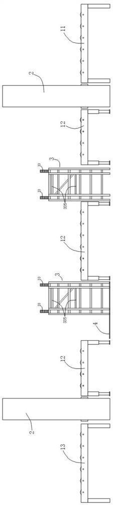
[0026] like figure 1 As shown, a production system for welding H-shaped steel includes a conveying roller 1, a setup device 2 and a flip device 3 for flip H-shaped steel; the setup machine 2 and the flip device 3 are along the conveyance. There are two in the conveying direction of the roller 1, and both of the flippers 3 are between two of the setup machines 2; the spacing between the two sets of setsters is greater than the H-type steel to be welded. The maximum length, and the spacing of the two flip device 3 is smaller than the minimum length of the H-shaped steel to be welded; the conveying roller 1 includes a first conveying roller 11, a second conveying roller 12, and a third transport roller 13, said The first conveying roller 11 and the third conveying roller 13 are respectively disposed on both sides of the two of the setup machine 2, wherein the first conveying roller 11 is disposed in a leading group in the conveying direction. On the input side of the stand 2, the thi...

Embodiment 2

[0049] In the present embodiment, the main structure is the same as that of the third embodiment, and will not be described later, the main difference between the embodiment and the first embodiment is:

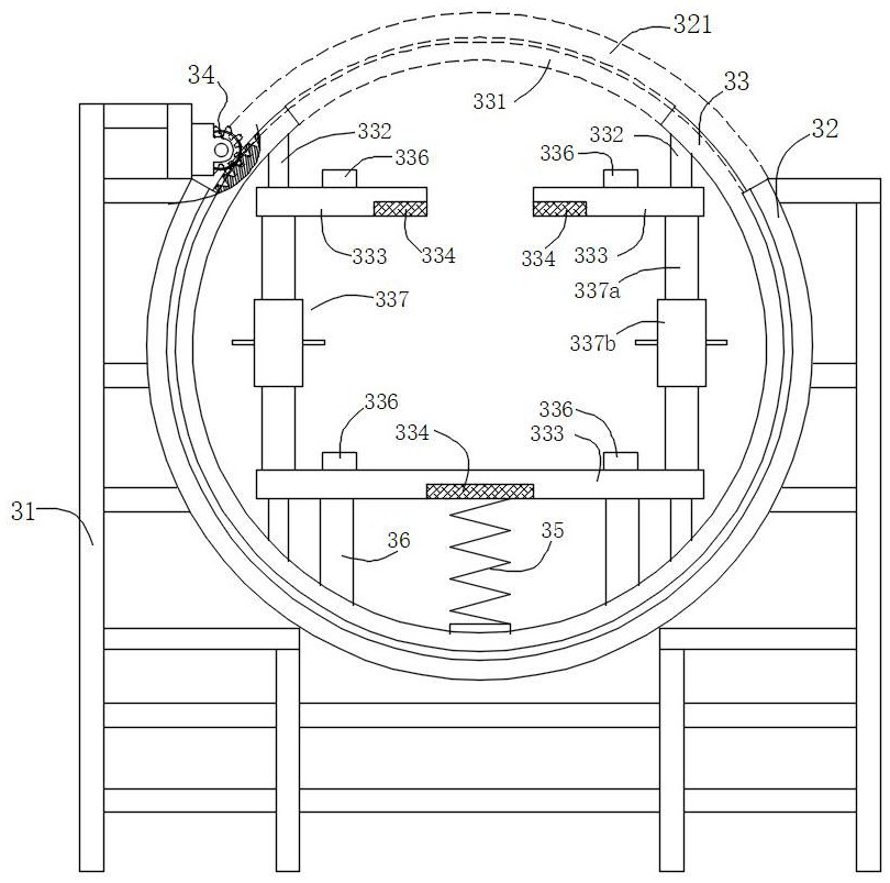
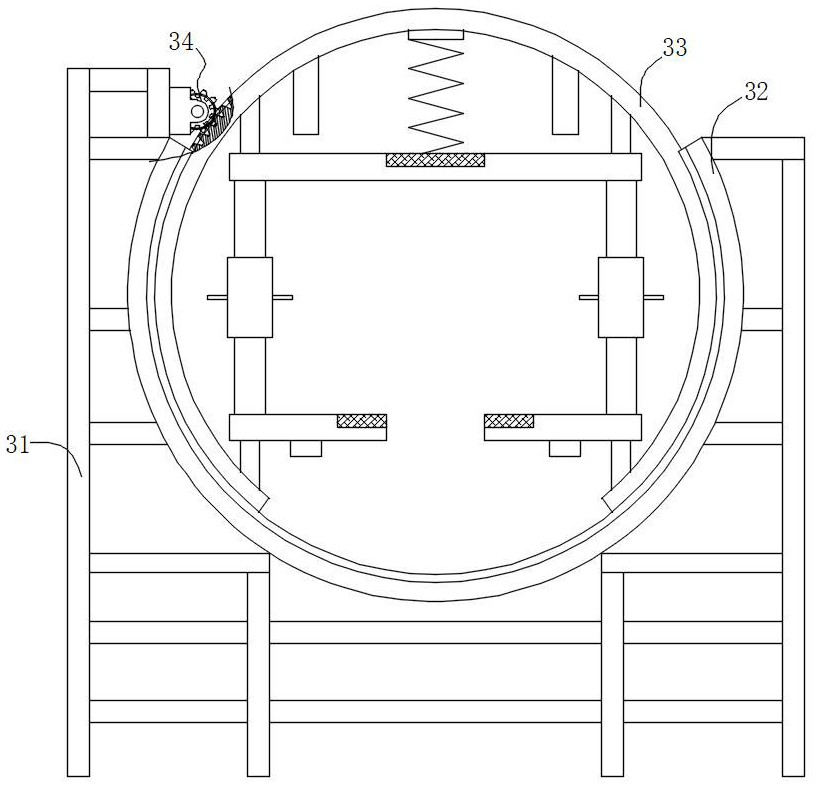
[0050] The lock adjustment mechanism 337 includes two support sleeves 337a set on the support rod 332, and both support sleeve 337a can move in the longitudinal direction of the support rod; one end of the two support sleeve 337a The opposite connection thread is rotated and connected by a threaded adjustment sleeve 337b. The support rod 332 has a limit slot disposed in the longitudinal direction, the support sleeve having a limiting screw disposed in the radial direction, and the end of the limiting screw remissions into the limit slot. Inside.

[0051] The two of the two support portions 333 are mounted at both ends from the two support sleeve 337a to each other, and are located in the support rod away from the two support portions of the second gap. The laminate differs from t...


PUM


Abstract

The invention discloses a production system for welding H-shaped steel, which includes a conveying roller table and an assembly machine, and also includes an overturning device, which is connected and arranged on the output side of the assembly machine; the overturning device includes an overturning bracket, and the overturning bracket is provided with Two integrally circular turning rails and rolling racks; the top of the flipping rails has a first gap arranged horizontally, and the flipping frame has a second gap; each side of the second gap has a The two ends of the supporting rod are connected to the inner side of the roll frame; both ends of the supporting rod have supporting parts arranged vertically inward, and the distance between the supporting parts at both ends is consistent with the width of the web; An electromagnet for fixing the flange is installed on the bracket; an overturn drive mechanism for driving the roll frame to rotate along the overturn track is also installed on the overturn bracket. The invention has the advantages of reasonable structural design, simple operation procedure, reduced labor intensity, improved assembly and welding efficiency, and the like.

Description

Technical field [0001] The present invention relates to the field of building materials production and processing, and in particular, there is a production system for welding H-shaped steel. Background technique [0002] H-type steel is a more optimized cross-sectional area, a strong weight than a more reasonable economic section high-efficiency profile, which is named after the cross-section is the same as the English alphabet "H". Since all parts of the H-steel are arranged in a right angle, the H-shaped steel has the advantages of strong anti-bending ability, simple construction, cost savings, and structural weight, and is widely used in various directions. [0003] Welding H-type steel is a suitable width of a suitable width, weld the flange and web in a continuous welding unit. At present, there are two welding methods of welding H-shaped steel, one is to place the web level, splicing the two flanges on both sides of the web, so that the web is located on the central positio...

Claims


Application Information

Patent Timeline
Patent Type & Authority Patents(China)
IPC IPC(8): B23K37/00B23K37/047B23K37/04
CPCB23K37/00B23K37/047B23K37/0426
Inventor 徐良春
Owner 重庆本浩建设工程有限公司
Why Eureka
Try Eureka