Automatic welding robot

A welding robot and automatic welding technology, applied in welding equipment, auxiliary welding equipment, welding/cutting auxiliary equipment, etc., can solve the problems of inconvenient pipe fixing, reduce welding efficiency, etc. Effect

Active Publication Date: 2020-08-11
湖南普东科技有限责任公司
View PDF6 Cites 7 Cited by
  • Summary
  • Abstract
  • Description
  • Claims
  • Application Information

AI Technical Summary

Problems solved by technology

[0004] The purpose of the present invention is to solve the shortcomings of the existing welding robot that it is not convenient to fix the pipe when welding, and secondly, when the pipe is docked, it needs to be rotated manually, and the angle is continuously adjusted for welding, which reduces the welding efficiency. The proposed automatic welding robot

Method used


Image

  • Automatic welding robot
  • Automatic welding robot
  • Automatic welding robot

Examples


Embodiment 1

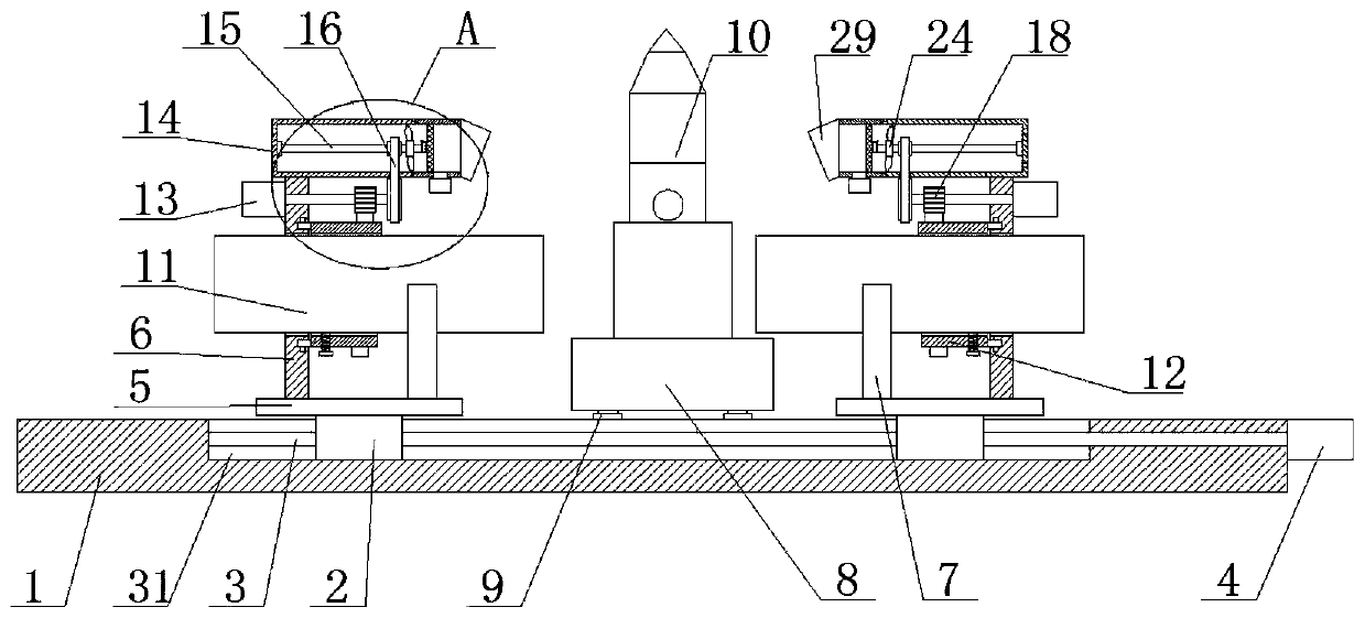
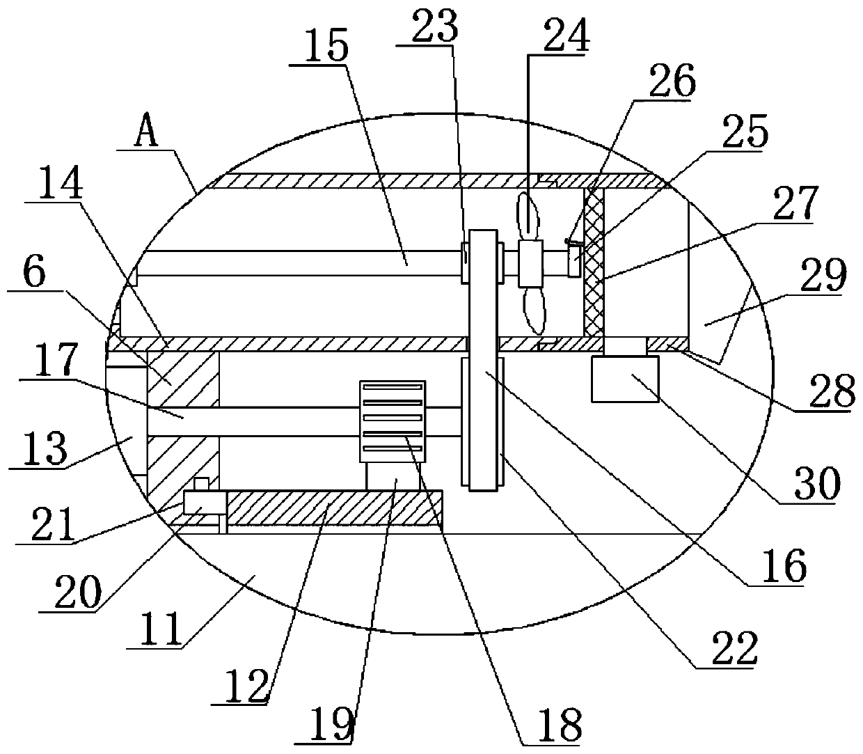
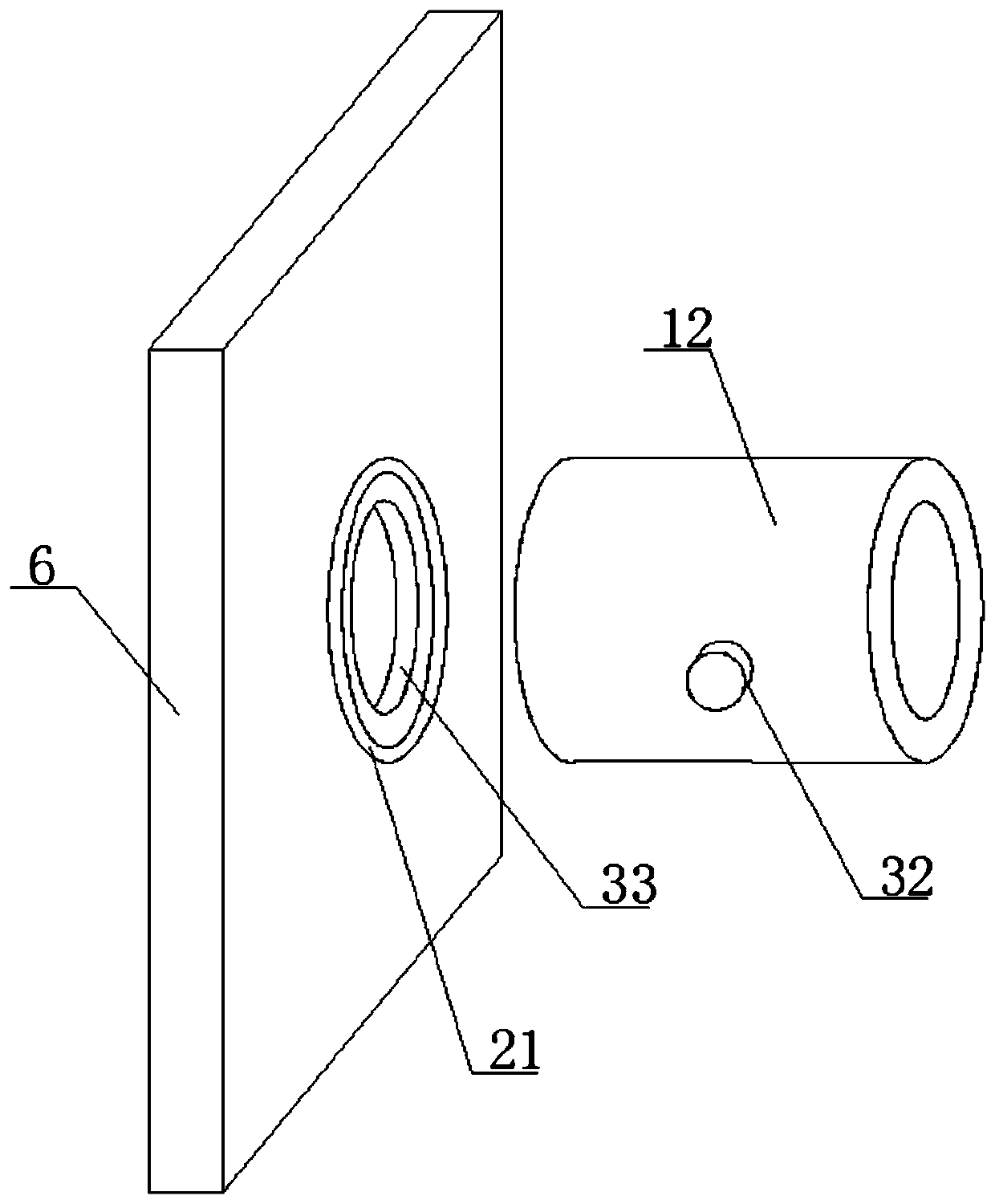
[0030] refer to Figure 1-5 , an automatic welding robot, including a base 1, the top of the base 1 is slidably connected with a welding robot body, the welding robot body includes a robot base 8 and a welding arm 10, and the top of the base 1 is slidably mounted with two fixed plates 5, two fixed plates The tops of 5 are fixedly equipped with support plates 6, and the sides of the two support plates 6 that are close to each other are rotatably connected with cylinders 12, and the two cylinders 12 are screwed with fixing bolts 32, and the two cylinders 12 are each Welded pipes 11 are movably connected, driving structures are fixedly connected to the two supporting plates 6, and the two cylinders 12 are respectively adapted to the two driving structures, and the tops of the two supporting plates 6 are fixedly connected to the dust suction cylinder 14 , the two dust suction cylinders 14 are provided with a dust suction structure, and the two dust suction structures are adapted t...

Embodiment 2

[0041] refer to Figure 1-5 , an automatic welding robot, including a base 1, the top of the base 1 is slidably connected with a welding robot body, the welding robot body includes a robot base 8 and a welding arm 10, and the top of the base 1 is slidably mounted with two fixed plates 5, two fixed plates The tops of 5 are all fixedly installed with support plates 6 by welding, and the sides of the two support plates 6 that are close to each other are rotatably connected with cylinders 12, and the two cylinders 12 are screwed with fixing bolts 32, and the two cylinders 12 Welded pipes 11 are movably connected inside, and the drive structure is fixedly connected to the two support plates 6 by screws. The two cylinders 12 are respectively adapted to the two drive structures, and the tops of the two support plates 6 are fixed by screws. A dust suction cylinder 14 is connected, and a dust suction structure is arranged inside the two dust suction cylinders 14, and the two dust sucti...


PUM


Abstract

The invention belongs to the technical field of robot welding, and particularly relates to an automatic welding robot. Aiming at the problems that when an existing welding robot is used for welding, pipes cannot be conveniently fixed; and then, when the pipes are subjected to butt joint, manual rotating is needed, and angles need to be continuously adjusted for welding, so that the welding efficiency is reduced, the following scheme is provided. According to the scheme, the robot comprises a base, a welding robot body is slidably connected to the top of the base, the welding robot body comprises a robot base and a welding arm, two fixing plates are symmetrically and slidably arranged at the top of the base, supporting plates are fixedly arranged at the tops of the two fixing plates, cylinders are rotatably connected to the sides, close to each other, of the two supporting plates, fixing bolts are connected to the two cylinders in a threaded mode, and welding pipes are movably connectedinto the two cylinders. According to the robot, the structure is simple, the operation is convenient, the pipes can be conveniently fixed, and manual rotating is not needed during welding, so that the welding efficiency is improved.

Description

technical field [0001] The invention relates to the technical field of robot welding, in particular to an automatic welding robot. Background technique [0002] Robot welding is very common in daily life, wherein the robot arm has a plurality of sequentially arranged joints and a driver connected to the robot control device, the welding tongs are fixed on the robot arm, and the robot control device is connected to the welding motor and the clamp driver. connected, and run an algorithm on the robot controller, which controls the drive of the robot arm to move the robot arm and regulates the gripper drive to apply a predetermined value to the welding electrode during resistance welding. The rated welding resistance, and the control of the welding motor, so that it can provide a predetermined electric energy to the welding electrode for welding. [0003] The existing welding robot can move in all directions through the mechanical arm, and can weld the tooling that needs to be ...

Claims


Application Information

Patent Timeline
Patent Type & Authority Applications(China)
IPC IPC(8): B23K37/053B01D46/00B01D46/10B01D53/04B08B15/04
CPCB23K37/0533B23K37/0538B08B15/04B01D46/0036B01D46/10B01D53/04B01D46/76
Inventor 陆剑峰周洪平
Owner 湖南普东科技有限责任公司
Why Eureka
Try Eureka