Knife sharpener

A knife sharpener and knife sharpening bar technology, which is applied in grinding/polishing equipment, grinding/polishing hand tools, metal processing equipment, etc., can solve the problem of time-consuming processing and assembly processes, affecting the use effect of blades and production efficiency Difficult to improve and other problems, to achieve the effect of simple and fast assembly, simplify processing and assembly procedures, and improve production efficiency

Pending Publication Date: 2020-08-11
中山市海巍厨具有限公司
View PDF0 Cites 0 Cited by
  • Summary
  • Abstract
  • Description
  • Claims
  • Application Information

AI Technical Summary

Problems solved by technology

And the blade of cutter generally comprises three parts of knife back, blade body, blade, and the included angle of blade is different, and blade included angle is often specifically set according to purpose etc., and the sharpening angle of the sharpening edge of existing knife sharpener Generally, it is a fixed sharpening angle, which does not have an adjustment function, and cannot adapt to different angles of blades. Often it is only hard to grind the angle of the blade into the sharpening angle of the sharpener, which cannot retain the angle of the blade itself. The effect of using the blade
In addition, the internal structure of the existing knife sharpener is relatively cumbersome and complicated, the processing and assembly processes are time-consuming, and the assembly efficiency is low, which makes it difficult to improve production efficiency and reduce production costs

Method used


Image

  • Knife sharpener
  • Knife sharpener
  • Knife sharpener

Examples


Embodiment Construction

[0016] It should be understood that the specific embodiments described here are only used to explain the present invention, not to limit the present invention.

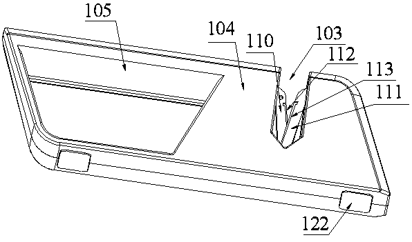
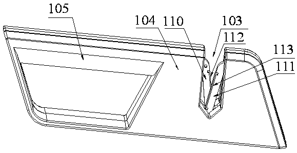
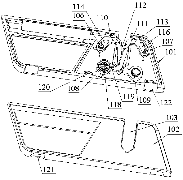
[0017] refer to Figure 1 to Figure 4 , an embodiment of a knife sharpener of the present invention is proposed, which includes a shell assembled by the first half shell 101 and the second half shell 102, and the shell includes a sharpening part 104 with a sharpening port 103, which is convenient The handle part 105 held by the human hand, the first half shell 101 and the second half shell 102 are positioned and fixed through the positioning column structure. The positioning column structure includes the first positioning column 106 located at the upper left side of the sharpening port 103, and the positioning post 106 located at the left upper end of the sharpening port. The second positioning post 107 at the upper right side of 103, the third positioning post 108 at the lower left side of the sharpening port 103, an...


PUM


Abstract

The invention discloses a knife sharpener. The knife sharpener comprises a shell formed by splicing a first half shell and a second half shell, the shell comprises a knife sharpening part and a handlepart, the first half shell and the second half shell are positioned and fixed through a positioning column structure, and the positioning column structure comprises a first positioning column, a second positioning column, a third positioning column and a fourth positioning column; the knife sharpener further comprises a first knife sharpening support arranged on the first positioning column and the fourth positioning column in a sleeving mode, a second knife sharpening support arranged on the second positioning column and the third positioning column in a sleeving mode, a first knife sharpening strip and a second knife sharpening strip, and the first knife sharpening support and the second knife sharpening support are distributed in a crossed mode to form an X-shaped included angle structure capable of clamping a knife edge; a first rail groove is formed in the upper end of the first knife sharpening support, a first spring cavity is formed in the lower end of the first knife sharpening support, and a first spring is arranged in the first spring cavity; and a second rail groove is formed in the upper end of the second knife sharpening support, a second spring cavity is formed in the lower end of the second knife sharpening support, and a second spring is arranged in the second spring cavity.

Description

technical field [0001] The invention relates to the technical field of knife sharpeners, in particular to a knife sharpener. Background technique [0002] Compared with traditional knife sharpeners, modern knife sharpeners have the advantages of fast sharpening speed, simple operation, convenient portability, and beautiful appearance. It is a scientific, practical, efficient and convenient sharpening tool, suitable for kitchen knives Outdoor knives, Damascus knives, ceramic knives and other knives are characterized by changing the traditional single-sided sharpening to double-sided sharpening, so that the method, angle, and efficiency of sharpening have undergone fundamental changes, and the sharpening efficiency has improved. Greatly improved, modern knife sharpeners are more and more widely used in daily life. And the blade of cutter generally comprises three parts of knife back, blade body, blade, and the included angle of blade is different, and blade included angle is ...

Claims


Application Information

Patent Timeline
IPC IPC(8): B24D15/08
CPCB24D15/08
Inventor 朱国栋
Owner 中山市海巍厨具有限公司
Why Eureka
Try Eureka