A side entry type booster mud cutting mechanism

A side-entry, mud-cutting technology, used in ceramic molding machines, manufacturing tools, etc., can solve the problems of high labor intensity, low mud-cutting efficiency, low degree of automation and work efficiency, and achieve low use and maintenance costs. Conducive to the effect of control and high degree of automation

Active Publication Date: 2020-08-18
张国阳
View PDF7 Cites 0 Cited by
  • Summary
  • Abstract
  • Description
  • Claims
  • Application Information

AI Technical Summary

Problems solved by technology

[0005] The invention provides a side-entry type booster mud cutting mechanism, which solves the problems of low mud cutting efficiency, high manual labor intensity, low degree of automation and low work efficiency

Method used


Image

  • A side entry type booster mud cutting mechanism
  • A side entry type booster mud cutting mechanism
  • A side entry type booster mud cutting mechanism

Examples


Embodiment Construction

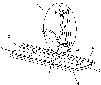
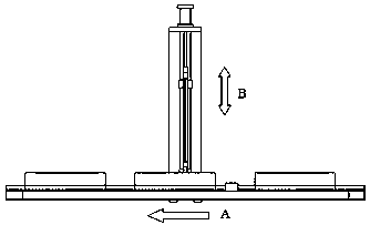
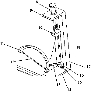
[0016] Such as figure 1 —3. Before using the device for cutting, the conveyor belt 5 is at a standstill. Place the combination of the pallet 1 and the mud column 2 on the conveyor belt 5, adjust the position of the suspension 14 on the guide rail 4 and fix it with the fixing screw 3. The mud cutting cylinder 8 moves its piston rod back into the cylinder chamber, and the slider 10 rises and drives one end of the pull rod 18, so that the knife rest 11 connected to the other end of the pull rod 18 rotates upward, and the booster rod 13 compresses the booster spring 15 to store Yes, complete the preparations.

[0017] When it is necessary to use this device to cut mud, the staff puts the mud column 2 to be cut on the supporting plate 1, and then the conveyor belt 5 is started, and the conveyor belt 5 transports the combination of the supporting plate 1 and the mud column 2 forward. When the position sensor 7. When the mud column 2 is detected, the conveyor belt 5 stops, the mud c...


PUM


Abstract

The invention discloses a side-entering type force increasing mud cutting mechanism. Before the side-entering type force increasing mud cutting mechanism works, the position of suspension is adjusted,and then the suspension is fixed with a fixing screw. A mud cutting cylinder acts, a piston rod of the mud cutting cylinder retreats, a sliding block moves upwards, a knife rack is pulled up by a pulling rod, a stop block presses downwards a force increasing spring, energy is stored, then a conveying belt is started, a combination of a support plate and a mud column is put onto the conveying belt, and the conveying belt drives the mud column to move forwards. When meeting with a position sensor, the conveying belt stops moving, the mud cutting cylinder acts to move the knife rack downwards till a mud cutting knife cuts off the mud column, at the moment, the stop block increases mud cutting force under the action of the force increasing spring, after the mud column is cut off, the knife rack retreats, and the force increasing spring stores energy and waits for the next time of work order. Through the side-entering type force increasing mud cutting mechanism, the problems that traditional mud cutting equipment is low in efficiency and low in automation degree, and cutting-off length cannot be adjusted are solved, meanwhile an automatic production line can be formed conveniently, andthe advantages of simple operation and good cut-off quality are achieved.

Description

technical field [0001] The invention relates to a device for automatically cutting mud strips according to needs during the production process of daily-use ceramics, and is especially suitable for a simple mud cutting device. Background technique [0002] In the production process of daily-use ceramic roll forming, it is necessary to cut the round clay strips processed from the raw material workshop into slices. The traditional process is to place the clay strips under the iron frame with multiple parallel steel wires. The iron frame is pressed down, and the mud bar is cut into multiple pieces at one time, and then the mud block is used one by one. Such a process method has defects. First, the steel wire bowed on the iron frame will be stretched after a short period of time. The length of the stretch is inconsistent, the steel wires are not parallel, and the thickness of the cut mud blocks is inconsistent, resulting in roll-formed blanks. The thickness and the density of th...

Claims


Application Information

Patent Timeline
Patent Type & Authority Patents(China)
IPC IPC(8): B28B11/14
CPCB28B11/14
Inventor 黎勤涛韦郁芬覃驿
Owner 张国阳
Why Eureka
Try Eureka