
Automobile skylight

A technology for car sunroofs and windows, applied in vehicle parts, engine sealing, roofs, etc., can solve the problems of smaller interior space, complex rail position structure, secondary injury to personnel, etc., to reduce the horizontal occupied area and improve the opening The effect of simple area and installation structure

Inactive Publication Date: 2020-08-11
马程
View PDF8 Cites 0 Cited by
  • Summary
  • Abstract
  • Description
  • Claims
  • Application Information

AI Technical Summary

Problems solved by technology

[0004] The object of the present invention is to provide a car sunroof to solve the problem that the existing car sunroof proposed in the above-mentioned background technology is usually provided with only one telescopic plate, and the telescopic plate also occupies an area when it shrinks, causing the maximum opening area of ​​the car sunroof to be smaller than that of the top of the car. half, and the structure of the existing car sunroof telescopic plate driving device occupies a large area, resulting in a smaller space in the car, which affects the comfort of use, and the existing car sunroof guide rail position structure is complicated, and the bottom cover is difficult to disassemble. It is convenient to clean the guide rails buried inside. The anti-pinch mechanism of the existing car sunroof is relatively rigid. The anti-pinch mechanism will automatically shrink when it detects that the resistance is too large, but the automatic shrinkage is too large, and it is easy to move with hair or clothes , causing secondary harm to personnel

Method used


Image

  • Automobile skylight
  • Automobile skylight
  • Automobile skylight

Examples


Embodiment Construction

[0029] The following will clearly and completely describe the technical solutions in the embodiments of the present invention with reference to the accompanying drawings in the embodiments of the present invention. Obviously, the described embodiments are only some, not all, embodiments of the present invention. Based on the embodiments of the present invention, all other embodiments obtained by persons of ordinary skill in the art without making creative efforts belong to the protection scope of the present invention.

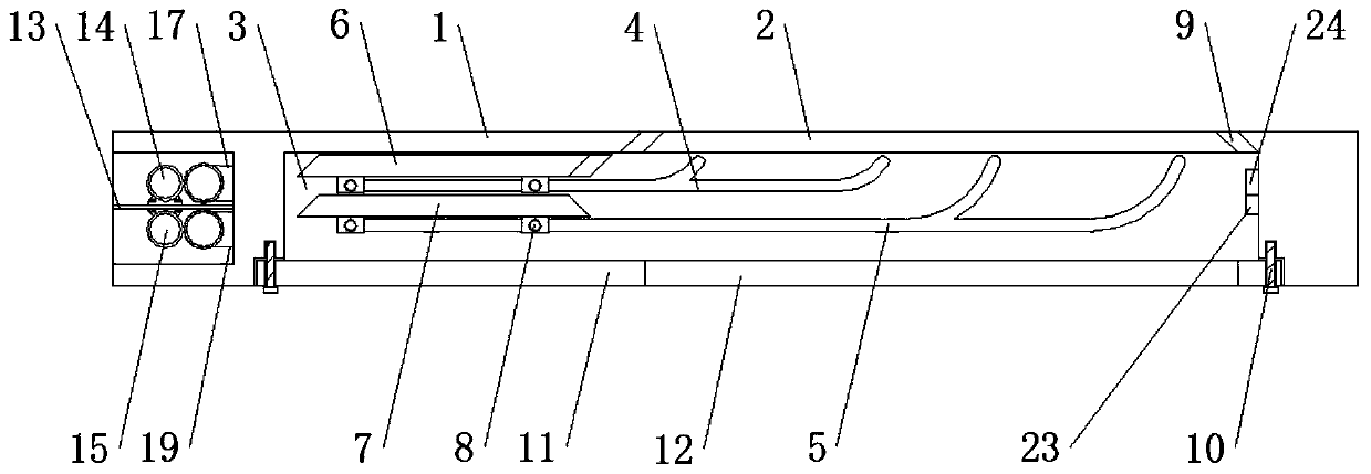
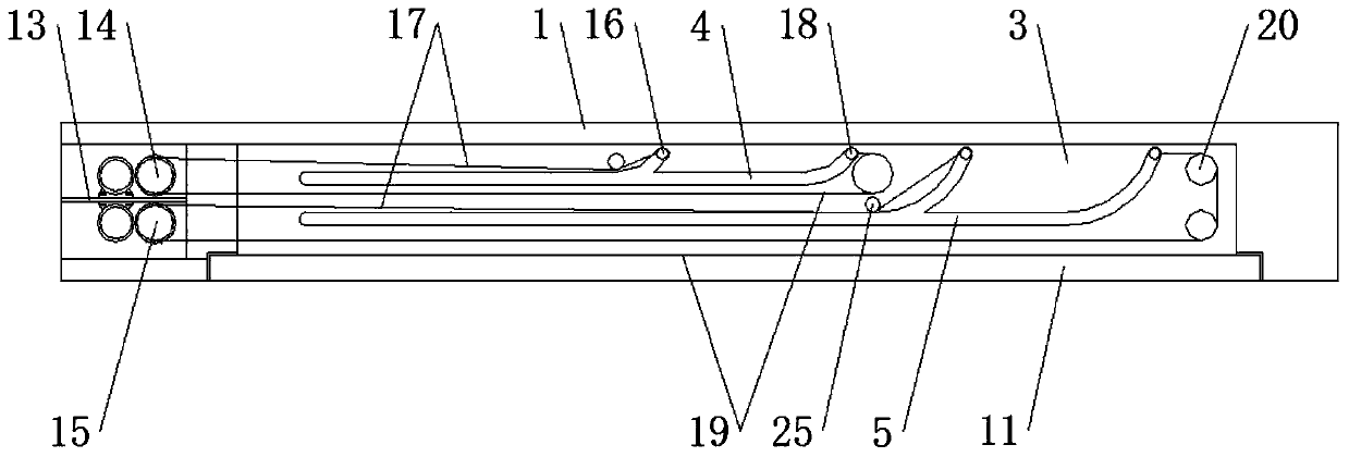
[0030] see Figure 1-8 , the present invention provides a technical solution: a car sunroof, such as figure 1 , figure 2 and Figure 4 As shown, a first window 2 is opened on the top of the top case 1, and a protective frame 3 is fixed on the bottom of the top case 1. The shape and size of the first window 2 are the same as the shape and size of the second window 12, and the centerline of the first window 2 Located on the same vertical line with the center...


PUM


Abstract

The invention discloses an automobile skylight. The automobile skylight comprises a top shell and bolts, a first window is formed in the top of the top shell, a protective frame is fixed at the bottomof the top shell, a first sliding groove and a second sliding groove are formed in the front side and the rear side of the protective frame, the second sliding groove is formed in the lower side of the first sliding groove, a first telescopic plate and a second telescopic plate are arranged in the protective frame, rotating shafts are rotatably connected to the bottoms of the first telescopic plate and the second telescopic plate, the front end and the rear end of the rotating shaft at the bottom of the first telescopic plate are slidably connected with the first sliding groove, and the frontend and the rear end of the rotating shaft at the bottom of the second telescopic plate are slidably connected with the second sliding groove. The automobile skylight is provided with the protectiveframe, the bolts and a bottom cover, the bolts are taken down by rotating, the bottom cover is taken down, the protective frame is exposed, and the first sliding groove and the second sliding groove are formed in the protective frame, so that the first sliding groove, the second sliding groove and other parts on the protective frame are cleaned conveniently, dust and other impurities are preventedfrom accumulating in the automobile skylight, and the service life of the automobile skylight is prolonged.

Description

technical field [0001] The invention relates to the technical field of automobile sunroofs, in particular to an automobile sunroof. Background technique [0002] The car sunroof is a window located on the top of the car, which has the advantages of low wind noise, high lighting rate and good ventilation effect. [0003] Existing car sunroofs are usually provided with only one telescopic plate, which also occupies an area when contracted, resulting in the maximum opening area of ​​the car sunroof being less than half of the top of the car, and the structure of the existing car sunroof’s telescopic plate driving device occupies a large area. As a result, the space inside the car becomes smaller, which affects the comfort of use, and the position structure of the guide rail of the existing car sunroof is complicated, and the bottom cover is difficult to disassemble, which is not convenient for cleaning the guide rail buried inside. The anti-pinch mechanism of the existing car s...

Claims


Application Information

Patent Timeline
Patent Type & Authority Applications(China)
IPC IPC(8): B60J7/02B60J7/043B60J7/057B60J7/00B60J10/90
CPCB60J7/00B60J7/02B60J7/043B60J7/057B60J10/90
Inventor 马程
Owner 马程
Learn More