
Rotary kiln lining pouring construction device and construction method thereof

A technology of construction equipment and rotary kiln, which is applied in the field of rotary kiln lining pouring construction equipment and its construction field, can solve the problems of reducing the construction efficiency of rotary kiln lining, waste of physical strength of construction personnel, etc., and achieves convenient laying operation, saving physical strength, improving Using the effect of the effect

Pending Publication Date: 2020-08-11
焦作诺尔曼炉业有限公司
View PDF0 Cites 1 Cited by
  • Summary
  • Abstract
  • Description
  • Claims
  • Application Information

AI Technical Summary

Problems solved by technology

[0003] At present, the inner lining of the rotary kiln is generally formed by laying refractory materials on the inner wall of the kiln body and then drying. However, when laying the inner lining in the kiln body, due to the long kiln body, people usually need to carry the materials to the construction position of the kiln body. Construction, which causes great physical waste to the construction personnel, and seriously reduces the construction efficiency of the rotary kiln lining. Therefore, it is necessary to study a fast and convenient rotary kiln lining construction equipment to solve the above problems

Method used


Image

  • Rotary kiln lining pouring construction device and construction method thereof
  • Rotary kiln lining pouring construction device and construction method thereof
  • Rotary kiln lining pouring construction device and construction method thereof

Examples


Embodiment Construction

[0035] The following will clearly and completely describe the technical solutions in the embodiments of the present invention with reference to the accompanying drawings in the embodiments of the present invention. Obviously, the described embodiments are only some, not all, embodiments of the present invention. Based on the embodiments of the present invention, all other embodiments obtained by persons of ordinary skill in the art without creative work, any modifications, equivalent replacements, improvements, etc., shall be included in the protection scope of the present invention Inside.

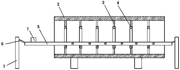
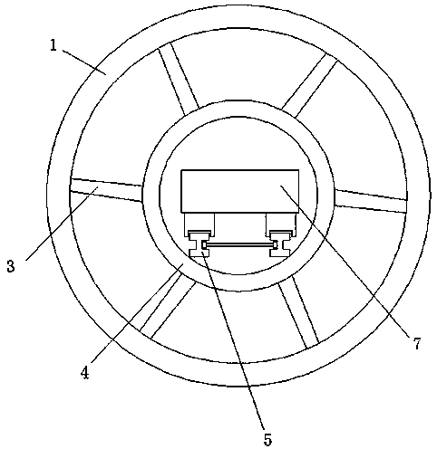
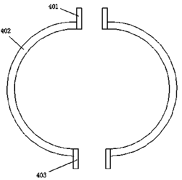
[0036] Such as Figure 1 to Figure 7 As shown, the rotary kiln lining pouring construction equipment in this embodiment includes the frame 1 arranged at the two outer ends of the rotary kiln body 2 and the support assembly, track assembly 5, and mobile trolley 7 arranged in the rotary kiln body 2 The support assembly is in contact with the track assembly 5, and the mobile trolley 7 is ar...


PUM


Abstract

The invention discloses a rotary kiln lining pouring construction device and a construction method thereof. The construction device comprises racks arranged at the two outer ends of a rotary kiln body, a supporting assembly, a rail assembly and a moving trolley, and the supporting assembly, the rail assembly and the moving trolley are arranged in the rotary kiln body. The supporting assembly makescontact with the rail assembly, and the moving trolley is arranged on the rail assembly. The construction method of the rotary kiln lining pouring construction device includes the following steps that S1, a sliding ring and a rail assembly are installed; S2, the moving trolley is installed; S3, a pouring material is put into the moving trolley; S4, the moving trolley is controlled to reach the construction position in the kiln body; S5, the pouring material in the moving trolley is unloaded; S6, after the pouring material at the bottom end of the inner side of the kiln body is laid, the kilnbody is controlled to rotate; S7, the moving trolley is used for pushing the pouring material to reach the construction position in the kiln body again; S8, the step S6 and the step S7 are repeated till pouring materials are completely laid on the inner side wall of the kiln body; and S9, construction operation is completed after the construction device is taken out.

Description

technical field [0001] The invention relates to the field of refractory material production, in particular to a rotary kiln lining pouring construction equipment and a construction method thereof. Background technique [0002] Rotary kiln refers to a rotary roasting kiln. Its function is to use rotation to process the materials in the kiln for high-temperature roasting. The lining of the rotary kiln refers to a structure that uses refractory materials to form a structure that is both heat-insulating and durable. [0003] At present, the inner lining of the rotary kiln is generally formed by laying refractory materials on the inner wall of the kiln body and then drying. When laying the inner lining in the kiln body, due to the long kiln body, people usually need to carry the materials to the construction position of the kiln body. Construction, which causes great physical waste to the construction workers, and seriously reduces the construction efficiency of the rotary kiln l...

Claims


Application Information

Patent Timeline
IPC IPC(8): F27B7/28F27B7/20F27D1/16
CPCF27B7/20F27B7/28F27D1/16
Inventor 王伟田铎铭焦顺杰
Owner 焦作诺尔曼炉业有限公司
Features
  • Generate Ideas
  • Intellectual Property
  • Life Sciences
  • Materials
  • Tech Scout
  • Unparalleled Data Quality
  • Higher Quality Content
  • 60% Fewer Hallucinations
Learn More