
Installation calibration method of laser radar

A technology of laser radar and calibration method, which is applied in the direction of radio wave measurement system, instrument, etc., can solve the problem of low accuracy, and achieve the effect of overcoming human error, saving cost and simple operation

Pending Publication Date: 2020-08-11
SHANGHAI UNIV OF ENG SCI
View PDF1 Cites 1 Cited by
  • Summary
  • Abstract
  • Description
  • Claims
  • Application Information

AI Technical Summary

Problems solved by technology

[0004] The purpose of the present invention is to provide a laser radar installation calibration method in order to overcome the defects of low accuracy in the above-mentioned prior art

Method used


Image

  • Installation calibration method of laser radar
  • Installation calibration method of laser radar
  • Installation calibration method of laser radar

Examples


Embodiment

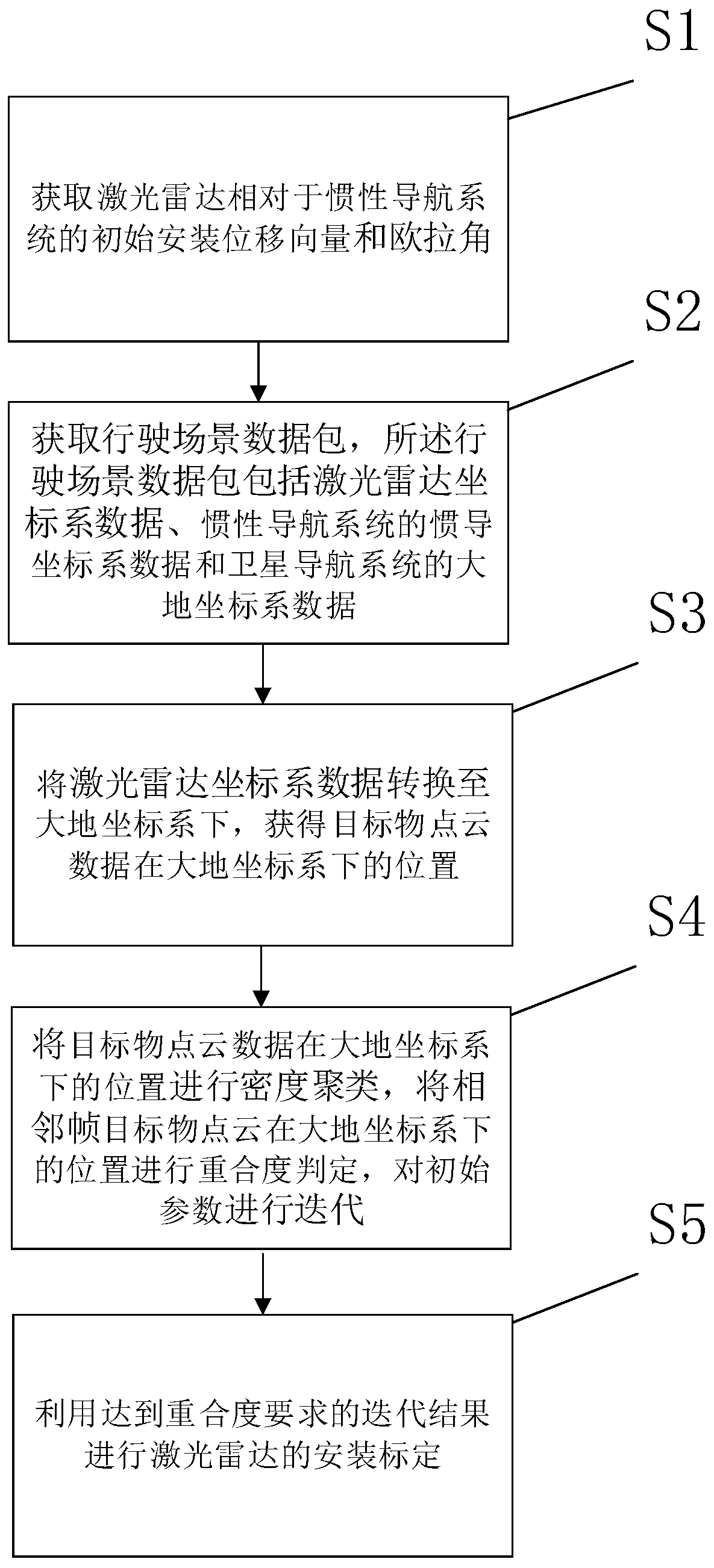
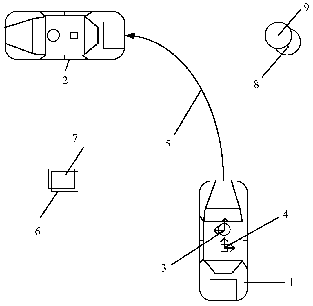
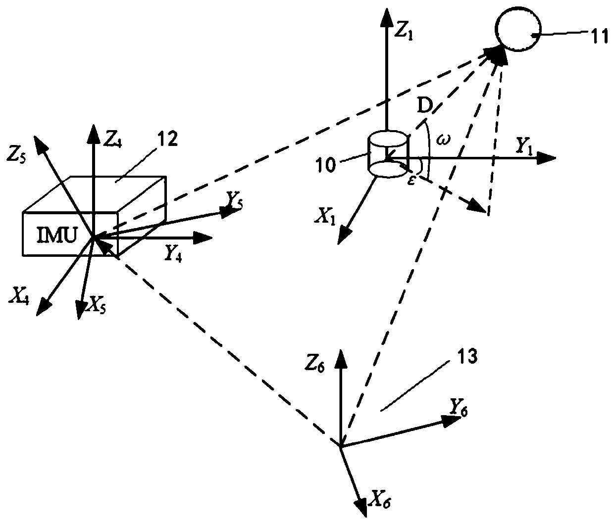
[0035] This embodiment provides a method based on the step-by-step iteration method and the Kd tree optimized density clustering algorithm (DBSCAN) to find the optimal placement parameters of the laser radar: after roughly measuring the initial installation positions of the laser radar and GNSS / INS, pass The step-by-step iteration method iterates the values ​​near the initial parameters, and the density clustering algorithm based on the Kd tree optimization determines the coincidence degree of the point cloud positions of adjacent frames converted to the earth coordinate system. During the step-by-step iteration process, the first After the local optimal parameters obtained in the first step, the global optimal solution is sought around the local optimal parameters in the first step by setting the small-scale step size in the second step, and a better for precise placement.

[0036] (1) Use a tape measure to roughly measure the initial relative installation displacement vector...


PUM


Abstract

The invention relates to an installation calibration method of a laser radar. The method comprises the following steps: acquiring an initial installation displacement vector (X, Y, Z) and an Euler angle (alpha, beta, gamma) of the laser radar relative to an inertial navigation system; acquiring a driving scene data packet, wherein the driving scene data packet comprises laser radar coordinate system data, inertial navigation coordinate system data of an inertial navigation system and geodetic coordinate system data of a satellite navigation system; converting the laser radar coordinate systemdata into a geodetic coordinate system to obtain the position of the target object point cloud data in the geodetic coordinate system; performing density clustering on the positions of the target object point cloud data in a geodetic coordinate system, performing overlap ratio judgment on the positions of adjacent frames of target object point clouds in the geodetic coordinate system, and performing iteration on initial parameters (X, Y, Z, alpha, beta and gamma); and carrying out installation calibration of the laser radar by using the iteration result meeting the overlap ratio requirement. Compared with the prior art, precision and resolution are high, personal errors in a traditional measurement method are overcome, manual control is not needed, operation is easy, and cost is saved.

Description

technical field [0001] The invention relates to the field of laser radar, in particular to a laser radar installation and calibration method. Background technique [0002] In recent years, artificial intelligence and data science have brought revolutionary progress to the automotive industry, and intelligent driving technology has been fully developed. Existing navigation and positioning systems usually use GNSS / INS (satellite navigation system / inertial navigation system) combination system for navigation and positioning. Satellite navigation systems provide speed and position information in the global coordinate system through satellite signals. Inertial navigation devices are usually divided into acceleration The meter and gyroscope can provide the directional acceleration and angular acceleration of the carrier. However, the GNSS and INS integrated navigation system still has its shortcomings. When GNSS is driving in urban canyons or tunnels, the antenna signal is blocke...

Claims


Application Information

Patent Timeline
IPC IPC(8): G01S7/497
CPCG01S7/497
Inventor 周志峰叶珏磊方宇吴明晖
Owner SHANGHAI UNIV OF ENG SCI
Learn More