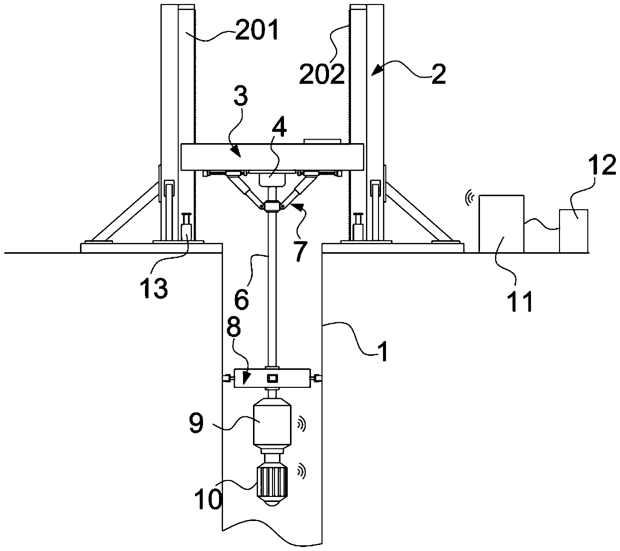
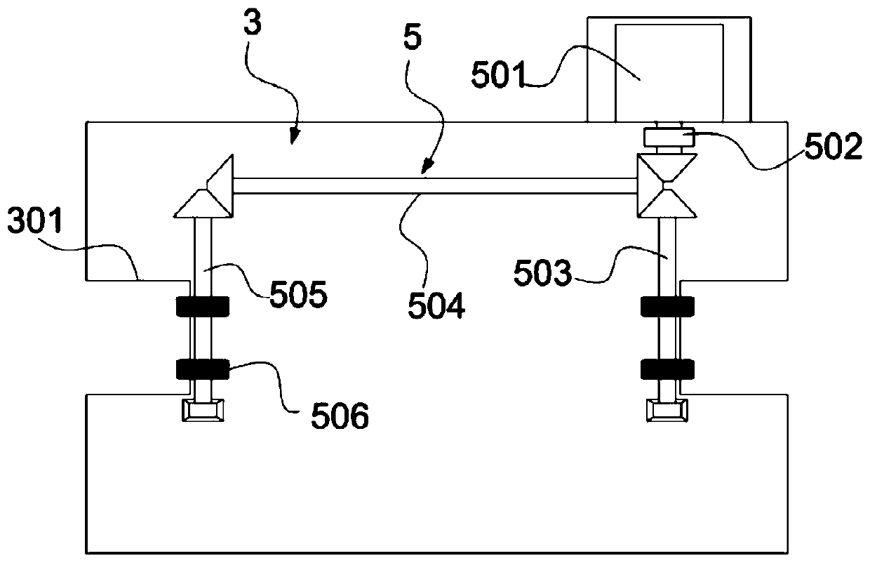
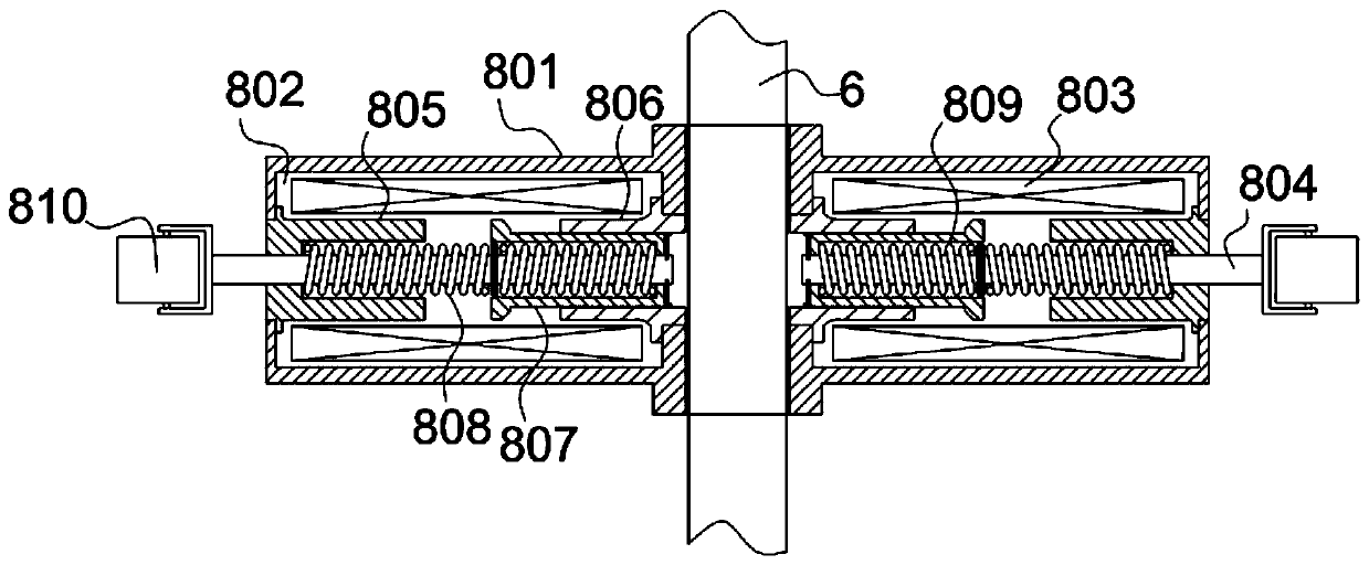
Geological survey hole imaging detection system

An imaging detection and geological survey technology, applied in geophysical measurement, supporting machines, mining equipment, etc., can solve problems such as poor lifting performance, inability to adjust, and probe head vibration, and achieve novel structural design, reduced space occupation, and stable implementation. and rising effect

Pending Publication Date: 2020-08-11
高军
View PDF0 Cites 5 Cited by
  • Summary
  • Abstract
  • Description
  • Claims
  • Application Information

AI Technical Summary

Problems solved by technology

In tunnel engineering, although there are applications of ultrasonic imaging technology and borehole imaging technology, there is no system in the prior art that has both ultrasonic imaging and borehole imaging functions and is used for tunnel geological detection. A set of equipment or system is inconvenient to use and the cost is high; moreover, the structure of the lifting support device used for this type of system or equipment is relatively complex and bulky, and the lifting performance is poor; at the same time, because it needs to be inserted into the formation hole, centering is required. , a centerer will be used, but most of the existing centerers use springs to center and buffer the push rod, but this structural support performance will cause the probe head on the push rod to vibrate or deflect while performing buffering. Shifting, safety, cushioning is relatively fixed and cannot be adjusted

Method used


Image

  • Geological survey hole imaging detection system
  • Geological survey hole imaging detection system
  • Geological survey hole imaging detection system

Examples


Embodiment Construction

[0031]In order to make the purpose, technical solutions and advantages of the embodiments of the present invention clearer, the technical solutions in the embodiments of the present invention will be clearly and completely described below in conjunction with the drawings in the embodiments of the present invention. Obviously, the described embodiments It is a part of embodiments of the present invention, but not all embodiments. The components of the embodiments of the invention generally described and illustrated in the figures herein may be arranged and designed in a variety of different configurations.

[0032] Accordingly, the following detailed description of the embodiments of the invention provided in the accompanying drawings is not intended to limit the scope of the claimed invention, but merely represents selected embodiments of the invention. Based on the embodiments of the present invention, all other embodiments obtained by persons of ordinary skill in the art wit...


PUM


Abstract

The invention belongs to the technical field of geological imaging systems, and discloses a geological survey hole imaging detection system, which comprises a lifting detection plate; a lifting driving mechanism, arranged in the lifting detection plate, and driving output ends extending out of the lifting detection plate being arranged on the two sides of the lifting driving mechanism respectively; lifting vertical frames, the number of the lifting vertical frames is two, and the two lifting vertical frames being located on the two sides of the lifting detection plate correspondingly, liftingmatching parts in transmission fit with the driving output ends being arranged on the inner sides of the lifting vertical frames in the height direction of the lifting vertical frames, and the liftingdetection plate can move up and down between the lifting vertical frames through transmission fit of the lifting matching parts and the lifting driving mechanisms; and a push rod, one end of the pushrod being connected to the bottom plate of the lifting detection plate through a rotating motor. The system has an ultrasonic imaging function and a drilling imaging function, two images can be collected and formed respectively, the geological structure in the tunnel can be known conveniently through the two images, and the system is more convenient to use.

Description

technical field [0001] The invention belongs to the technical field of geological imaging systems, and in particular relates to a geological survey hole imaging detection system. Background technique [0002] Ultrasonic imaging and borehole imaging technologies are often used in geological structure detection, and these two technologies are commonly used in the field of coal mines. In tunnel engineering, although there are applications of ultrasonic imaging technology and borehole imaging technology, there is no system in the prior art that has both ultrasonic imaging and borehole imaging functions and is used for tunnel geological detection. A set of equipment or system is inconvenient to use and the cost is high; moreover, the structure of the lifting support device used for this type of system or equipment is relatively complex and bulky, and the lifting performance is poor; at the same time, because it needs to be inserted into the formation hole, centering is required. ...

Claims


Application Information

Patent Timeline
Patent Type & Authority Applications(China)
IPC IPC(8): G01V11/00E21F17/18E21B47/002F16M11/24F16M11/04F16M11/08F16M11/18
CPCE21F17/18F16M11/04F16M11/08F16M11/18F16M11/24G01V11/005
Inventor 高军林晓谭发刚黎建华杨立云贾超吴德兴项小珍刘凯文黄正凯熊晓晖蔡荣喜王东旭王更峰李波
Owner 高军
Why Eureka
Try Eureka