
Wiring method, manufacturing method, wiring structure and rotary electrical machine of rotating electrical machine

A technology of rotating electrical machines and wiring methods, applied in the shape/style/structure of winding conductors, manufacturing motor generators, electromechanical devices, etc., can solve problems such as output reduction, reactive power loss, copper loss, etc., and achieve suppression of circulating current Effect

Active Publication Date: 2022-07-26
ODAWARA ENG
View PDF7 Cites 0 Cited by
  • Summary
  • Abstract
  • Description
  • Claims
  • Application Information

AI Technical Summary

Problems solved by technology

[0005] Most of the circulating current is reactive current which causes reactive power loss (e.g. reduced output of motor) and copper loss

Method used


Image

  • Wiring method, manufacturing method, wiring structure and rotary electrical machine of rotating electrical machine
  • Wiring method, manufacturing method, wiring structure and rotary electrical machine of rotating electrical machine
  • Wiring method, manufacturing method, wiring structure and rotary electrical machine of rotating electrical machine

Examples


Embodiment Construction

[0050] Hereinafter, embodiments of the present invention will be described with reference to the accompanying drawings.

[0051] First, refer to Figure 1 to Figure 10 The first embodiment is described.

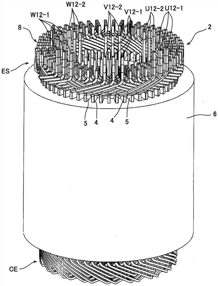
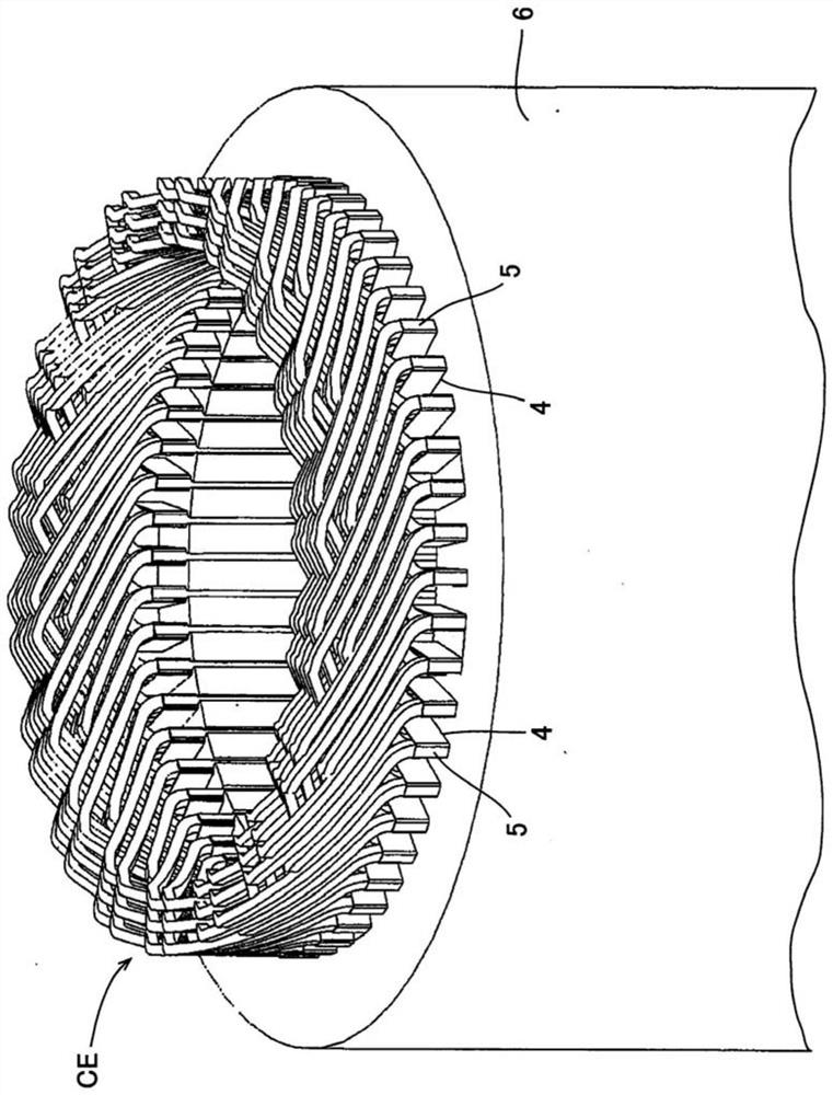
[0052] figure 1 and figure 2 The stator 2 having the wiring structure of the rotary electric machine according to the present embodiment is shown. figure 1 shows the entire stator 2, and figure 2 The coil end CE side of the stator 2 is shown.

[0053] The stator 2 comprises a cylindrical core 6 with a plurality of circumferentially arranged slots 4 and coils 8 for three phases (U-phase, V-phase, W-phase) by inserting U-shaped coil segments into the slots 4 It is formed by connecting the ends of the coil segments in the insertion direction thereof according to a predetermined pattern. The coil 8 has a six-layer structure.

[0054] Each coil segment is inserted from the coil end CE side, and the end side of the insertion direction (ie figure 1 The end portions of t...


PUM


Abstract

In the present invention, in-phase coil segments are inserted into each set of three circumferentially consecutive slots. If the slots in each group of three are denoted as A, B, and C, the six groups are denoted U1 to U6, and the slot y of group Ux is denoted as slot Uxy, the coils starting from slot U1A are routed To pass through one turn of the stator in the order of slots U1A→U2B→U3B→U5C→U6A, and connect to the slot U1A of the next turn. In this case, coil segments with large span widths are used for U1A→U2B connections and U3B→U4C connections, while coil segments with narrow span widths are used for U5C→U6A connections. In the case of forming a rotating electric machine in which coil segments of the same phase are inserted in every three circumferentially continuous slots, circulating current can be suppressed.

Description

technical field [0001] The present invention relates to a wiring method and wiring structure for a rotating electrical machine (rotating electrical machine) such as a motor or a generator, and more particularly, to a wiring structure for three-phase (U-phase, V-phase, W-phase) A wiring method and wiring structure of a rotary electric machine having a coil composed of a U-shaped or the like coil segment having a pair of slot insertion portions. The present invention also relates to a method of manufacturing a rotating electrical machine and a rotating electrical machine. Background technique [0002] As a coil of a stator or a rotor of a rotating electric machine, a so-called segment coil is known, in which coil segments formed by processing a straight wire into a U shape are inserted into a plurality of slots arranged along the circumferential direction of the stator or rotor, respectively. , and the free end sides of these coil segments are electrically connected to each o...

Claims


Application Information

Patent Timeline
Patent Type & Authority Patents(China)
IPC IPC(8): H02K3/28
CPCH02K3/28H02K15/0081H02K15/064H02K2213/03
Inventor 宫胁伸郎
Owner ODAWARA ENG
Learn More