Rotating electric machine

A technology for rotating motors and armatures, applied to synchronous motors, electromechanical devices, electrical components, etc.

Pending Publication Date: 2021-10-22
DENSO CORP
View PDF1 Cites 0 Cited by
  • Summary
  • Abstract
  • Description
  • Claims
  • Application Information

AI Technical Summary

Problems solved by technology

In this case, even with the known armature coil forming method, there is still a limit to the reduction in the circumferential dimension of the intersection area of ​​the head of each coil section, and therefore, it may not be possible to flexibly design the rotating electrical machine. specification changes

Method used


Image

  • Rotating electric machine
  • Rotating electric machine
  • Rotating electric machine

Examples


Embodiment Construction

[0060] Hereinafter, exemplary embodiments will be described with reference to the accompanying drawings. It should be noted that for the sake of clarity and understanding, the same components having the same functions in the overall description are given the same reference numerals as much as possible, and in order to avoid redundant description, the same components will not be described repeatedly.

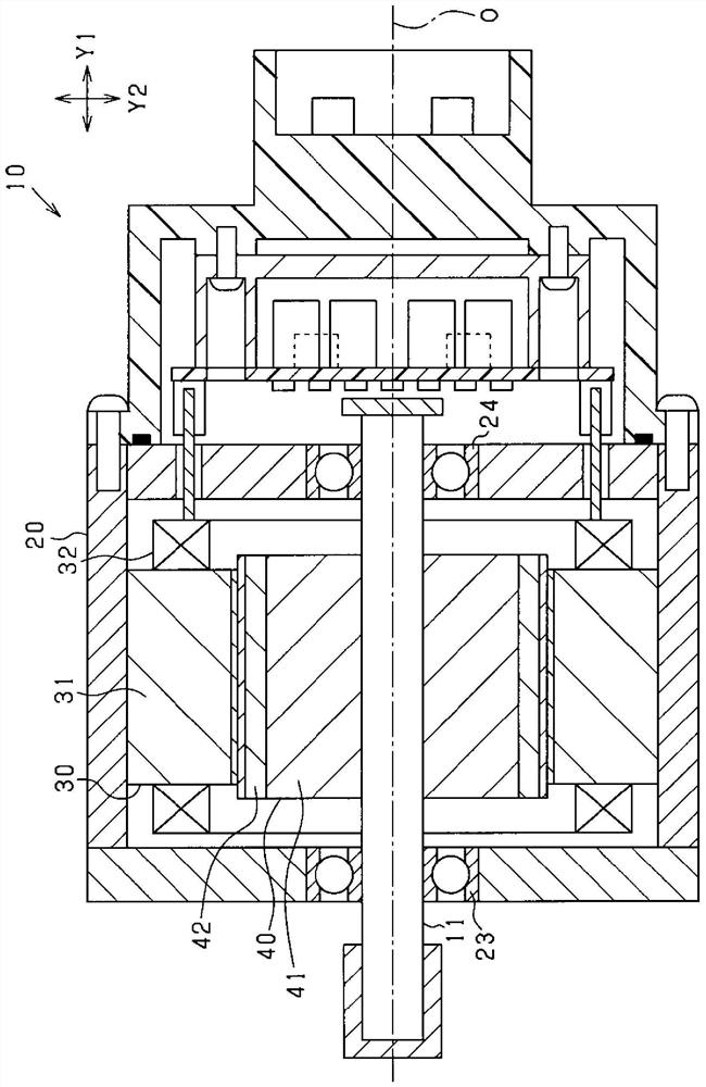
[0061] figure 1 The overall structure of the rotating electric machine according to the exemplary embodiment is shown.

[0062] In the present embodiment, the rotating electric mechanism is an electric motor 10 used in a vehicle. Specifically, the motor 10 is a three-phase permanent magnet synchronous motor. That is, the motor 10 is a brushless motor. In addition, the motor 10 may include only one three-phase coil belonging to a single system or two three-phase coils respectively belonging to two systems.

[0063] Such as figure 1 As shown, the motor 10 includes: a housing 2...


PUM


Abstract

A rotating electric machine includes a multi-phase armature coil wound on an armature core. The armature coil is formed of electrical conductor groups each being a bundle of electrical conductor segments and having a pair of leg portions and a connecting portion that connects the leg portions. The connecting portion is bent radially with respect to a circumferential direction. The electrical conductor groups are paired such that each pair of the electrical conductor groups consists of a first electrical conductor group and a second electrical conductor group both belonging to a same phase of the armature coil. The circumferential pitch between the leg portions of the first electrical conductor group is greater than that between the leg portions of the second electrical conductor group. In each pair of the electrical conductor groups, the connecting portions of the first and second electrical conductor groups are arranged to axially overlap each other.

Description

technical field [0001] The present disclosure relates to a rotating electric machine. Background technique [0002] A known rotating electrical machine comprises an armature having multi-phase armature coils wound on an armature core. In addition, there is also known a method of forming an armature coil by (1) inserting the two legs of each substantially U-shaped coil section from one axial side of the armature core to the armature core. in the corresponding slots; and (2) engaging each pair of corresponding parts of the legs of the coil sections protruding outside the corresponding slots on the other axial side of the armature core (for example, see Japanese Patent No. JP5702179B2). [0003] More specifically, according to a known method, a substantially S-shaped portion is formed in the head of each coil segment so as to reduce the circumference of the intersection area at the coil ends where the head passes radially through the armature coil. to size. Accordingly, it i...

Claims


Application Information

Patent Timeline
Patent Type & Authority Applications(China)
IPC IPC(8): H02K3/28H02K3/04H02K1/26H02K3/12H02K3/50H02K3/34H02K3/38
CPCH02K3/28H02K3/04H02K1/265H02K3/12H02K3/505H02K3/34H02K3/38H02K2213/03H02K3/14H02K1/276H02K1/16H02K11/33H02K21/14
Inventor 远藤宽士田村晓斗
Owner DENSO CORP
Why Eureka
Try Eureka