Drive system of AC motor and elevator equipment using the drive system

An AC motor and drive system technology, which is applied to AC motor control, elevators in buildings, control systems, etc., can solve the problems of increasing the number of components, rising costs, and inability to obtain circulating current suppression control, and achieves suppression of circulating current, The effect of improving reliability

Inactive Publication Date: 2017-11-03
HITACHI LTD
View PDF3 Cites 0 Cited by
  • Summary
  • Abstract
  • Description
  • Claims
  • Application Information

AI Technical Summary

Problems solved by technology

Therefore, when the patterns of the control intervals are different among the power conversion devices, a sufficient effect of the circulating current suppression control cannot be obtained.
[0013] In addition, in the technique disclosed in Patent Document 2, since an LC filter having an impedance equal to that of each power conversion device is connected, the number of components increases, resulting in an increase in the size of the power conversion device and a decrease in cost. rise

Method used


Image

  • Drive system of AC motor and elevator equipment using the drive system
  • Drive system of AC motor and elevator equipment using the drive system
  • Drive system of AC motor and elevator equipment using the drive system

Examples


no. 1 example

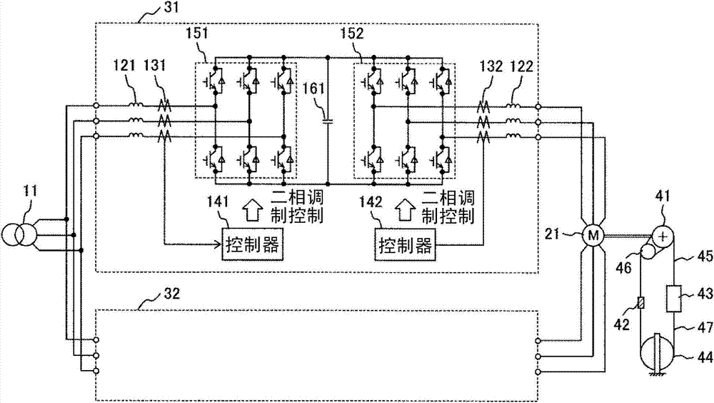
[0039] figure 1 A drive system for an AC motor as a first embodiment of the present invention is shown. This drive system is used to drive the elevator.

[0040] In this embodiment, the power conversion device 31 and the power conversion device 32 connected in parallel convert the three-phase alternating current with constant voltage and constant frequency input from the commercial power supply 11 into three-phase alternating current with variable voltage and variable frequency output. The three-phase AC motor 21 is driven by the outputted three-phase AC power. The three-phase AC motor 21 has double windings, thereby suppressing circulating current flowing between the power converters as will be described later. In addition, as the three-phase AC motor 21, an induction motor, a permanent magnet synchronous motor, or the like is used.

[0041] In the elevator of this embodiment, the sling 45 is wound around the sheave 41 and the pulley 46, and a counterweight 42 and an ele...

no. 2 example

[0057] Figure 5 A drive system for an AC motor as a second embodiment of the present invention is shown. Figure 5 It is a block diagram showing the converter sections 151a, 151b (CONV) and the inverter sections 152a, 152b (INV), and the specific main circuit configuration is omitted in the figure. In addition, the description of the elevator part is omitted. In addition, since the controller and the power source side current detector of the power conversion device 32 are the same as those of the power conversion device 31 , descriptions of these components are omitted here.

[0058] and figure 1 The same as the first embodiment of the above, the inverter part 152a in the power conversion device 31 is PWM controlled by the controller 142a in a two-phase modulation manner, and the inverter part 152b in the power conversion device 32 is also controlled by a not shown The controller performs PWM control with two-phase modulation. In addition, the AC output of the inverter s...


PUM


Abstract

The invention provides the drive system of an AC motor and elevator equipment provided with the drive system. When an AC motor is driven by a parallel multiple modular inverter in a two-phase modulation and control manner, the cycle current of the inverter is reliably suppressed without upsizing the equipment and increasing the cost. The drive system comprises a parallel multiple connection type power conversion devices (31, 32) and a three-phase AC motor driven by the power conversion devices (31, 32). The three-phase AC motor is composed of two three-phase windings on each part of a dual winding structure. One three-phase winding is connected with the AC output part of the inverter portion of the power conversion device (31), and the other three-phase winding is connected with the AC output part of the inverter portion of the power conversion device (32).

Description

technical field [0001] The present invention relates to an AC motor drive system that drives an AC motor by connecting multiple inverters in parallel, and elevator equipment using the drive system. Background technique [0002] Conventionally, when driving high-speed or large-capacity AC variable-speed drive systems such as large-scale elevator equipment, power is increased by multiplying unit power conversion devices that use semiconductor switching elements and perform pulse-width modulation control. capacity. As an example of multiplexing, there is known a power conversion system in which a plurality of unit power conversion devices are connected in parallel and operated in parallel based on the same three-phase voltage command. [0003] Generally, in such a power conversion system, a delay time occurs in a voltage command due to an operation delay of a control circuit and a variation in switching speed of a semiconductor switching element. When voltage commands of a pl...

Claims


Application Information

Patent Timeline
Patent Type & Authority Patents(China)
IPC IPC(8): H02P27/06H02M5/458H02M7/5387B66B11/04
CPCB66B11/04H02M5/458H02M7/5387H02P27/06
Inventor 松本洋平森和久大沼直人蛭田清玄加藤可奈子
Owner HITACHI LTD
Why Eureka
Try Eureka