power conversion device

A power conversion device and circuit technology, applied in the direction of high-efficiency power electronic conversion, output power conversion device, electrical components, etc., can solve the problems of large measurement error, inability to suppress circulating current with high precision, low responsiveness of current sensor, etc.

Active Publication Date: 2018-06-29
TOYOTA JIDOSHA KK
View PDF6 Cites 0 Cited by
  • Summary
  • Abstract
  • Description
  • Claims
  • Application Information

AI Technical Summary

Problems solved by technology

[0011] However, if the responsiveness of the current sensor is low, the measurement error of the current value measured by the current sensor will increase, so the circulating current may not be able to be suppressed with high accuracy.

Method used


Image

  • power conversion device
  • power conversion device
  • power conversion device

Examples


Embodiment Construction

[0030] Hereinafter, embodiments of the present invention will be described based on the drawings.

[0031] Figure 4 It is a figure which shows an example of the structure of the power supply apparatus 101 which is an embodiment of a power conversion apparatus. The power supply device 101 is, for example, an example of a power supply system for a vehicle that is installed in a vehicle such as a car and distributes power to each load installed in the vehicle. The power supply device 101 includes, for example, a power supply circuit 10 and a control circuit 50.

[0032] The power supply circuit 10 is an example of a power conversion circuit that has at least two or more ports, and has a function of selecting any two ports from these ports to perform power conversion between the selected two ports . The power supply circuit 10 of this embodiment has four ports, for example, a first port 60 a, a second port 60 c, a third port 60 b, a fourth port 60 d, and a converter 11.

[0033] The ...


PUM


Abstract

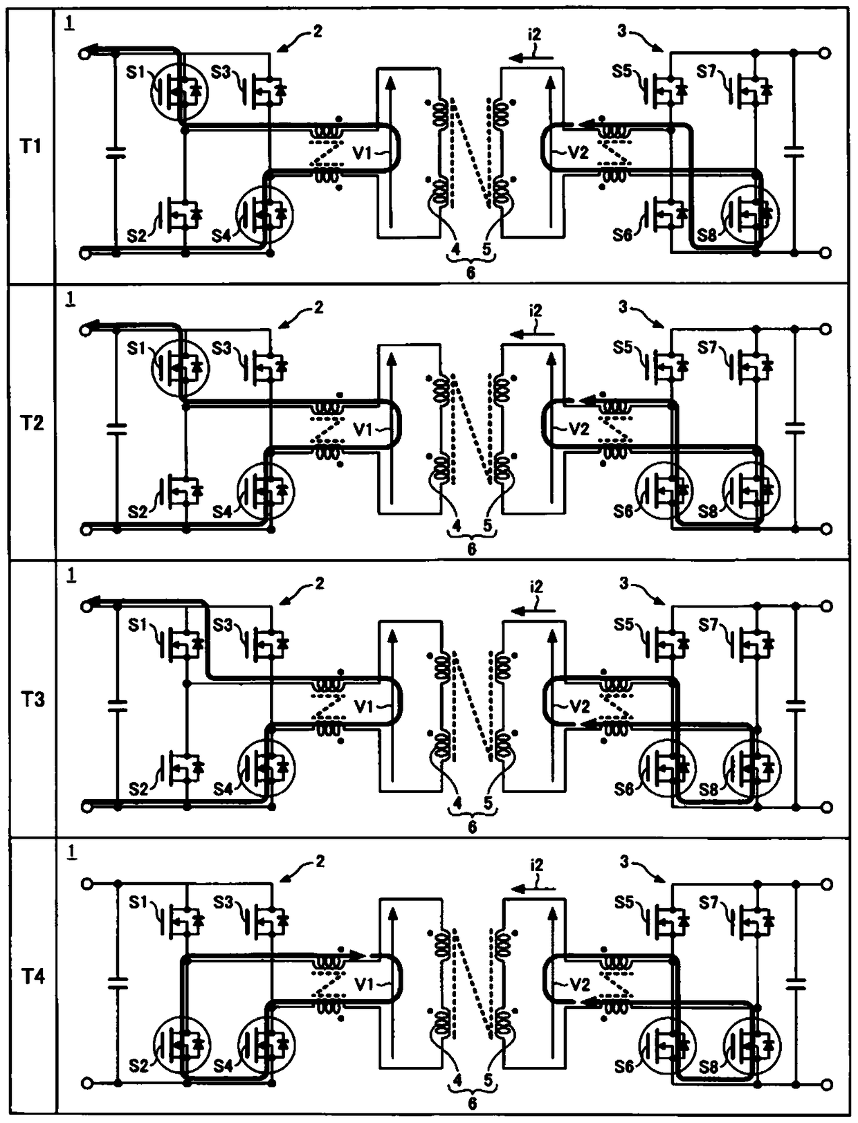
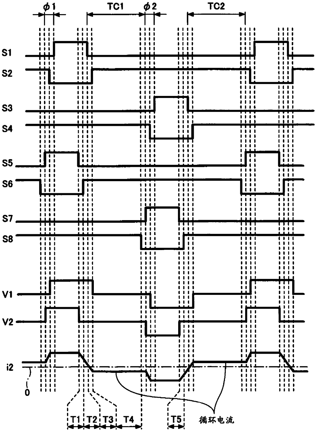
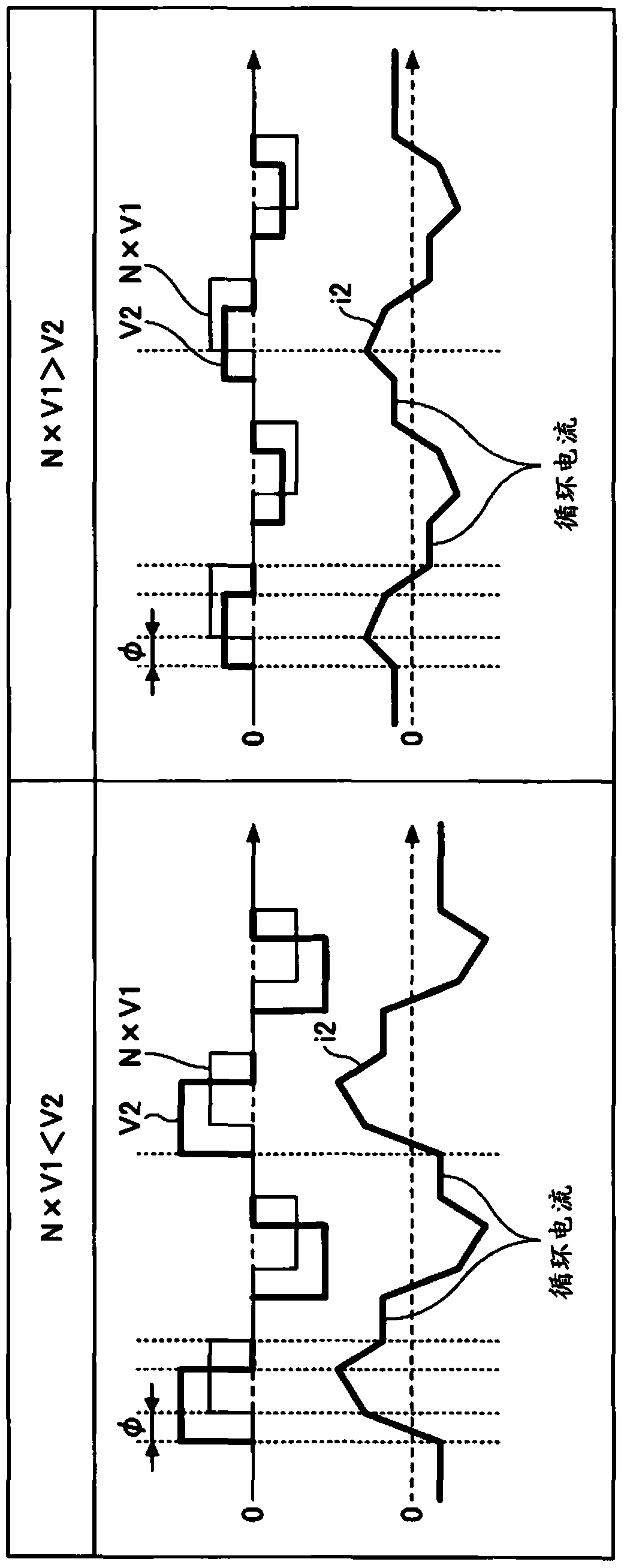
The present invention provides a power conversion device capable of suppressing circulating current with high precision even if the responsiveness of a current sensor is low. The period between the time when the first arm is turned off and the time when the seventh arm is turned on is defined as the first period, the period in which the first period is delayed by the response delay time of the current sensor is defined as the first integration period, and the third period is defined as the first integration period. When the period between the time when the arm is turned off and the time when the fifth arm is turned on is defined as the second period, and the period in which the second period is delayed by the response delay time of the current sensor is defined as the second integration period, the control unit operates at the first The first integral value obtained by integrating the measurement value of the current sensor during the integration period is corrected so that the first integral value obtained by integrating the measurement value of the current sensor is close to zero, or the second integration value obtained by integrating the measurement value of the current sensor during the second integration period is corrected. The moment of disconnection of the seventh arm is corrected in such a way that the integral value is close to zero.

Description

Technical field [0001] The present invention relates to a power conversion device. Background technique [0002] There is known a power conversion device as follows, including: a transformer having a primary side coil and a secondary side coil; a primary side full bridge circuit in which a primary side coil of the transformer is provided in the bridge portion; and a secondary side full bridge circuit, The secondary side coil of a transformer is provided in the bridge part (for example, refer patent document 1). The primary-side full-bridge circuit and the secondary-side full-bridge circuit respectively have a pair of arm circuits in which arms are provided on a high side and a low side. The power conversion device controls the phase difference between the switches of the primary-side full-bridge circuit and the secondary-side full-bridge circuit so that power is transmitted between the primary-side full-bridge circuit and the secondary-side full-bridge circuit. [0003] Patent Do...

Claims


Application Information

Patent Timeline
Patent Type & Authority Patents(China)
IPC IPC(8): H02M3/335H02M1/00
CPCH02M3/3353H02M3/33561H02M3/33584Y02B70/10H02M1/0048H02M3/33546
Inventor 内原诚文佐佐木一行
Owner TOYOTA JIDOSHA KK
Why Eureka
Try Eureka