Drainage assembly and cooking device

A technology of drainage components and drainage parts, which is applied to steam cooking utensils, cooking utensils, household appliances, etc., can solve problems such as difficulty in flowing into drainage holes, breeding of bacteria, manual cleaning, etc.

Active Publication Date: 2020-08-14
GUANGDONG MIDEA KITCHEN APPLIANCES MFG CO LTD +1
View PDF18 Cites 0 Cited by
  • Summary
  • Abstract
  • Description
  • Claims
  • Application Information

AI Technical Summary

Problems solved by technology

[0002] When using a steamer to cook food, the condensed water in the cooking cavity will drop to the bottom plate of the whole box. Usually, drain holes are set on the bottom plate to drain the condensed water on the bottom plate. However, in order to prevent food residues from entering the drain hole and clogging Drainage cha

Method used


Image

  • Drainage assembly and cooking device
  • Drainage assembly and cooking device
  • Drainage assembly and cooking device

Examples


Embodiment 1

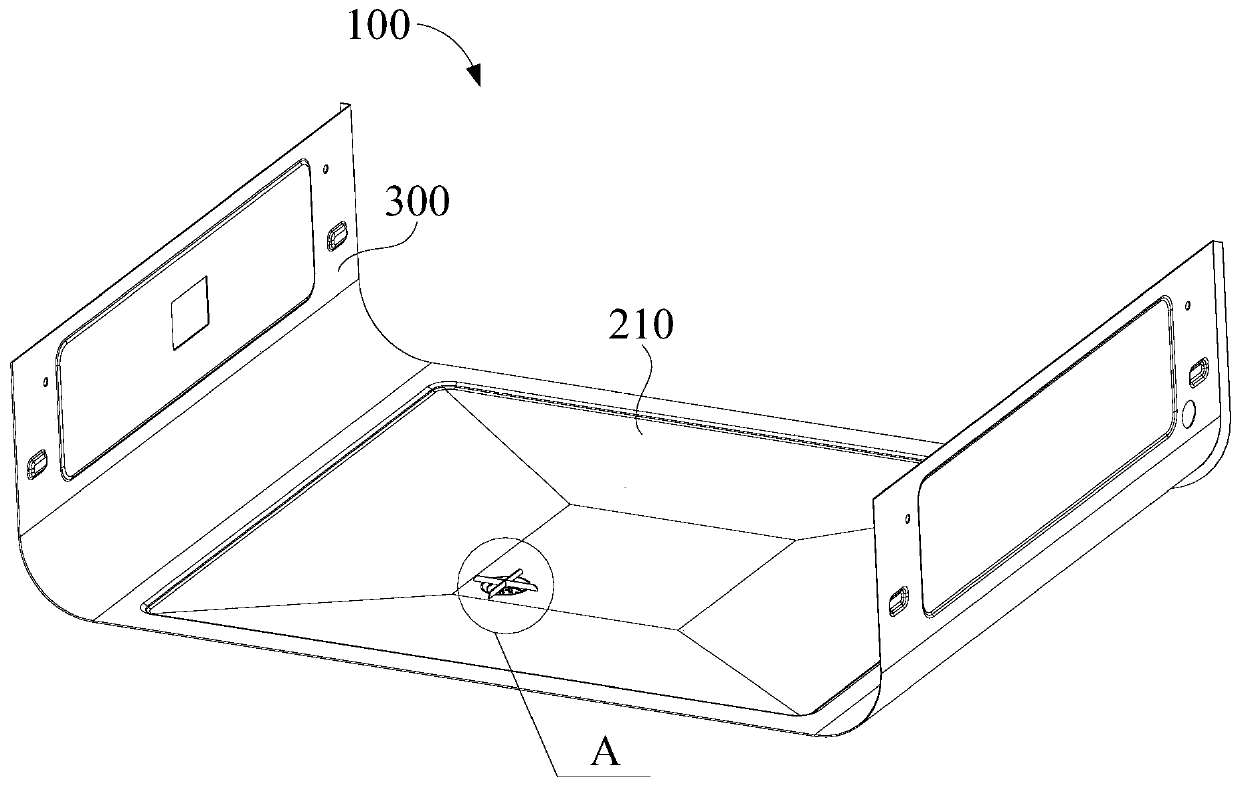
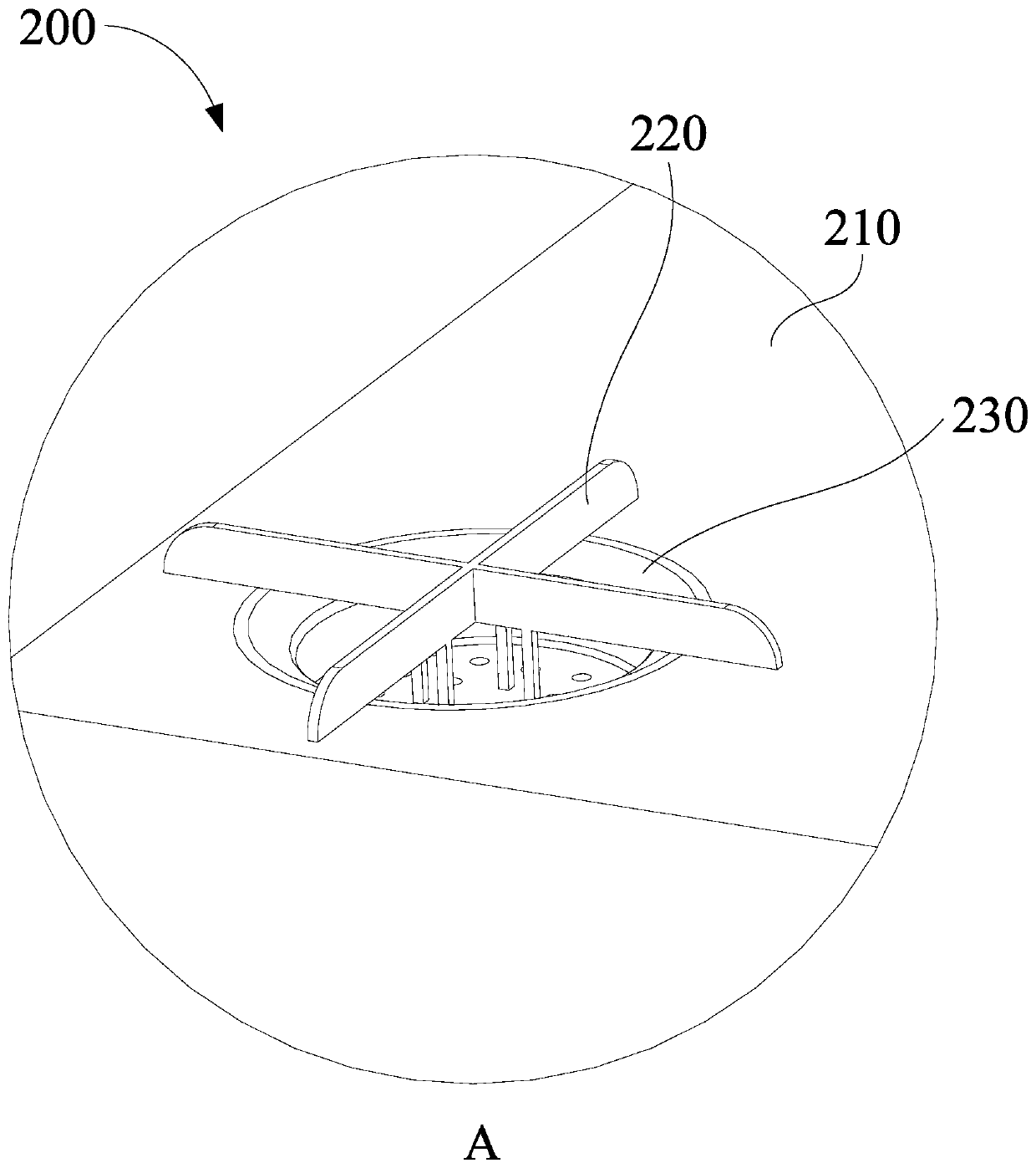
[0046] combine figure 1 and figure 2 As shown, the first aspect of the present invention proposes a drainage assembly, including: a plate body 210 and at least one drain plate 220, the plate body 210 is provided with a drain part 202, the drain part 202 is used to discharge condensed water, at least one drain The plate 220 is arranged on the plate body 210, that is, at least one drain plate 220 protrudes from the end surface of the plate body 210. When the condensed water gathers at the drain part 202, the drain plate 220 can reduce the contact area between the condensed water and the plate body 210, That is to say, where the drainage plate 220 is provided, the condensed water does not contact the surface of the plate body 210, because the contact area between the condensed water and the plate body 210 is reduced, thereby destroying the surface tension of the water, and then allowing the condensed water to pass through the drain smoothly 202 is discharged, and the drain plat...

Embodiment 2

[0048] combine figure 1 , figure 2 and image 3 As shown, in a specific embodiment based on the first embodiment, the drainage part 202 is configured as a through hole through which condensed water can be discharged. Specifically, the drainage plate 220 covers the through hole at most. When the condensed water accumulates When the through hole is located, the drainage plate 220 can reduce the contact area between the condensed water and the plate body 210, thus destroying the surface tension of the water, so that the condensed water can be smoothly discharged through the through hole. When the drainage plate 220 partially covers the through hole , the drain plate 220 can drain the condensed water, when the condensed water is drained to the end of the drain plate 220, the end of the drain plate 220 is located above the through hole, so that the condensed water can drip into the through hole And discharge, improve the discharge smoothness of condensed water.

[0049] Further...

Embodiment 3

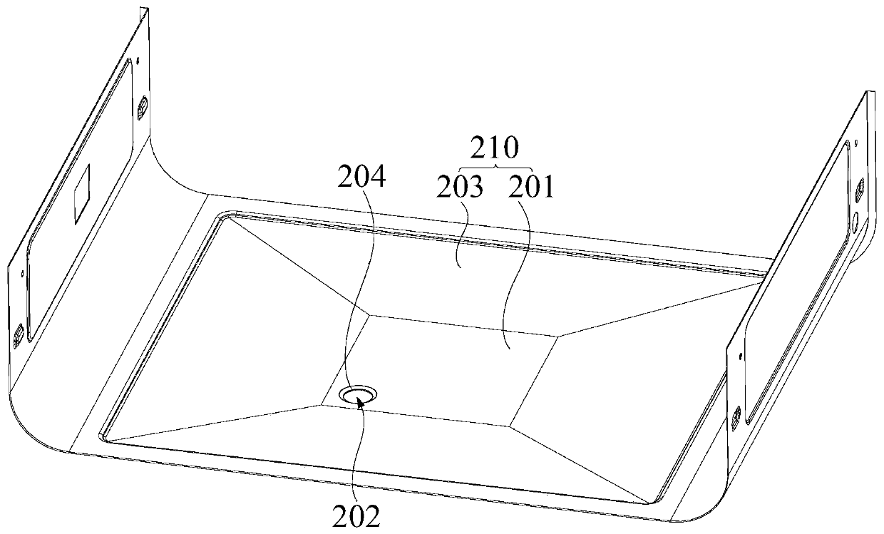
[0056] combine image 3 and Figure 4 As shown, on the basis of Embodiment 1 and Embodiment 2, the drainage assembly further includes: a first annular ramp 234 and a second annular ramp 204, the first annular ramp 234 is located on the second backboard away from the first backboard On one side, the second annular ramp 204 is integrally formed on the plate body 210, the second annular ramp 204 is arranged at one end of the through hole, the first annular ramp 234 and the second annular ramp 204 are configured in a flared shape, The first annular ramp 234 is adapted to be erected on the second annular ramp 204 .

[0057] In this embodiment, the first annular ramp 234 is configured in a flaring shape, that is, the upper surface of the first annular ramp 234 is provided with a guide surface, and the guide surface acts as a guide for condensed water, and the condensed water can flow along the The guide surface flows into the filter cavity to increase the discharge speed of conden...


PUM


Abstract

The invention provides a drainage assembly and a cooking device.The drainage assembly comprises a plate body and at least one drainage plate, and a drainage part is arranged on the plate body; at least one drainage plate is arranged on the plate body; any one of the at least one drainage plate at most partially covers the drainage part; when the condensed water is gathered at the water dischargingpart,the drainage plate can reduce the contact area of condensed water and the plate body, namelyat the position wherethe drainage plate is arranged,condensate water is not in contact with the surface of the plate body, and the contact area of the condensate water and the plate body is reduced, so that the surface tension effect of the water is destroyed, the condensate water can be smoothly drained through the drainage part, the workload of manually cleaning accumulated water on the plate body is reduced, and the problem of bacterium breeding caused by accumulation of the condensate water isalso avoided.

Description

technical field [0001] The invention belongs to the technical field of food processing equipment, and in particular relates to a drainage assembly and a cooking device. Background technique [0002] When using a steamer to cook food, the condensed water in the cooking cavity will drop to the bottom plate of the whole box. Usually, drain holes are set on the bottom plate to drain the condensed water on the bottom plate. However, in order to prevent food residues from entering the drain hole and clogging Drainage channels will have small drain holes on the bottom plate. Due to the tension of the water, the condensed water will cover the top of the drain holes and it is difficult to flow into the drain holes, causing the condensed water to accumulate on the bottom plate and require manual cleaning or the breeding of bacteria. problem occurs. Contents of the invention [0003] The present invention aims to solve one of the technical problems existing in the prior art or relat...

Claims


Application Information

Patent Timeline
IPC IPC(8): A47J27/04A47J36/38
CPCA47J27/04A47J36/38A47J2027/043
Inventor 林健赵涛任志文裴杰任孟珂周宇
Owner GUANGDONG MIDEA KITCHEN APPLIANCES MFG CO LTD
Why Eureka
Try Eureka