

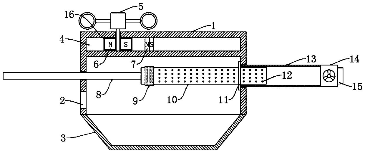
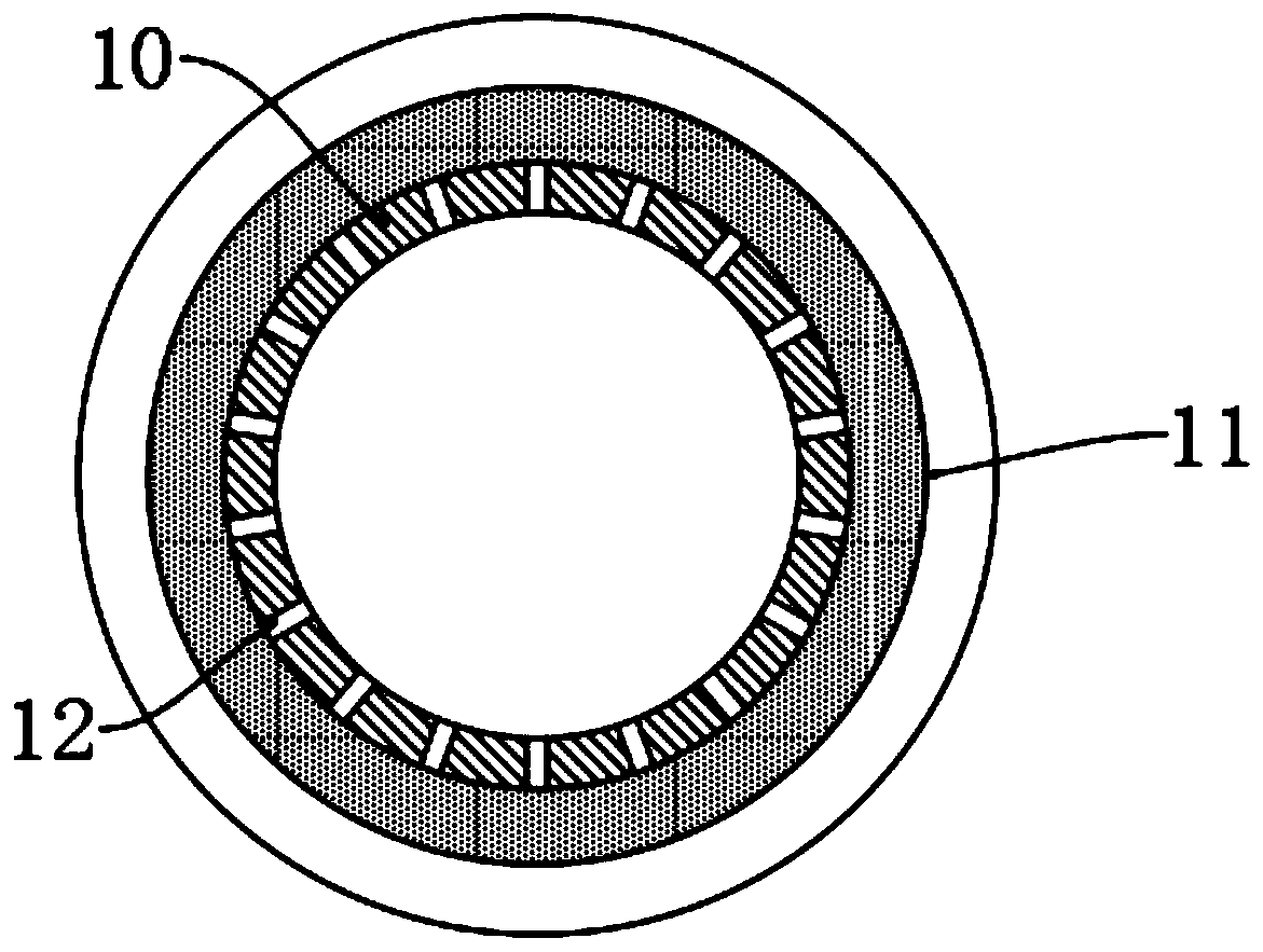
Tubular dust collector for construction site
A technology for construction sites and dust collectors, which is applied in the direction of chemical instruments and methods, dispersed particle filtration, combined devices, etc., can solve the problems of worker influence, high repair and maintenance costs, and shorten the service life of machines, so as to prevent air intake holes from clogging, Effect of preventing local accumulation and improving safety
- Summary
- Abstract
- Description
- Claims
- Application Information
AI Technical Summary
Problems solved by technology
Method used
Image


Examples
Embodiment Construction
[0016] The following will clearly and completely describe the technical solutions in the embodiments of the present invention with reference to the accompanying drawings in the embodiments of the present invention. Obviously, the described embodiments are only some, not all, embodiments of the present invention.
[0017] In describing the present invention, it should be understood that the terms "upper", "lower", "front", "rear", "left", "right", "top", "bottom", "inner", " The orientation or positional relationship indicated by "outside", etc. is based on the orientation or positional relationship shown in the drawings, and is only for the convenience of describing the present invention and simplifying the description, rather than indicating or implying that the referred device or element must have a specific orientation, so as to Specific orientation configurations and operations, therefore, are not to be construed as limitations on the invention.
[0018] refer to Figure ...
PUM
 Abstract
Description
Claims
Application Information