
Micro-fluidic chip

A microfluidic chip and chip technology, applied in the field of microfluidics, can solve problems such as complex structure, small chip size, and impossibility

Inactive Publication Date: 2020-08-14
北京森美希克玛生物科技有限公司
View PDF15 Cites 0 Cited by
  • Summary
  • Abstract
  • Description
  • Claims
  • Application Information

AI Technical Summary

Problems solved by technology

[0003] However, due to the small size and complex structure of the chip, the transfer operation of some liquid samples is prone to errors or cannot be realized, which leads to the failure of subsequent detection tests on liquid samples.

Method used


Image

  • Micro-fluidic chip
  • Micro-fluidic chip

Examples


Embodiment Construction

[0022] In order to make the purpose, technical solutions and advantages of the embodiments of the present invention clearer, the technical solutions in the embodiments of the present invention will be clearly and completely described below in conjunction with the drawings in the embodiments of the present invention. Obviously, the described embodiments It is a part of embodiments of the present invention, but not all embodiments. The components of the embodiments of the invention generally described and illustrated in the figures herein may be arranged and designed in a variety of different configurations.

[0023] Accordingly, the following detailed description of the embodiments of the invention provided in the accompanying drawings is not intended to limit the scope of the claimed invention, but merely represents selected embodiments of the invention. Based on the embodiments of the present invention, all other embodiments obtained by persons of ordinary skill in the art wi...


PUM

PropertyMeasurementUnit
The inside diameter ofaaaaaaaaaa

Abstract

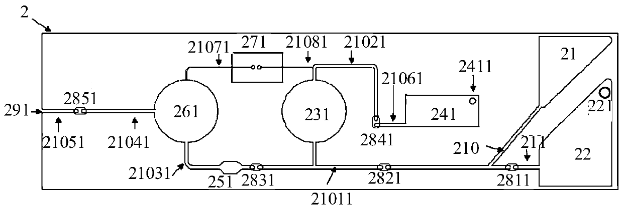
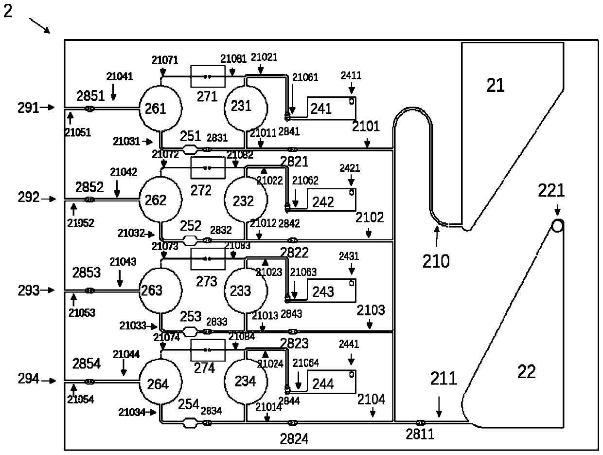
The invention provides a micro-fluidic chip, and belongs to the technical field of micro-fluidic control. The micro-fluidic chip comprises a chip substrate, the chip substrate is provided with a sample pool, a liquid output port and a liquid conveying pipeline communicated with the sample pool and the liquid output port. The sample pool is provided with an opening for injecting a liquid sample; afunctional pool is arranged on the liquid conveying pipeline in a communicating mode, and the liquid output port is externally connected with a negative pressure device so that negative pressure can be formed at the liquid output port. The liquid sample is transferred from the sample pool to the liquid output port so that the transfer operation of the liquid sample on the micro-fluidic chip is realized, and subsequent tests are facilitated.

Description

technical field [0001] The invention relates to the field of microfluidic technology, in particular to a microfluidic chip. Background technique [0002] The microfluidic analysis chip constructs various microfunctional components on the chip through microfabrication technology, thereby forming an analysis system with microfluidic control. Microfluidic chips have broad application prospects in many fields. Among them, biomedicine is currently the main application field of microfluidic chips. For example, microfluidic chips used for clinical testing have the most extensive market in my country. [0003] However, due to the small size and complex structure of the chip, the transfer operation of some liquid samples is prone to errors or cannot be realized, which leads to the failure of subsequent detection tests on liquid samples. Contents of the invention [0004] The purpose of the present invention is to provide a microfluidic chip, which can more accurately realize the ...

Claims


Application Information

Patent Timeline
IPC IPC(8): B01L3/00
CPCB01L3/50273B01L2400/0487
Inventor 魏清泉
Owner 北京森美希克玛生物科技有限公司
Learn More