Sand blasting machining equipment with automatic feeding and discharging function

A technology for automatic loading and unloading and sandblasting, which is applied in metal processing equipment, abrasive jet machine tools, used abrasive processing devices, etc. and automatic cutting, etc., to achieve the effect of reasonable structure design and improved efficiency

Inactive Publication Date: 2021-08-27
CHONGQING IND POLYTECHNIC COLLEGE
View PDF3 Cites 2 Cited by
  • Summary
  • Abstract
  • Description
  • Claims
  • Application Information

AI Technical Summary

Problems solved by technology

[0004] Existing sandblasting processing equipment is usually suitable for single-piece sandblasting processing, and cannot realize automatic loading and unloading. For the sandblasting processing of large quantities of workpieces, the existing sandblasting processing equipment is difficult to meet the requirements of continuous processing. Requirements, low sandblasting efficiency

Method used


Image

  • Sand blasting machining equipment with automatic feeding and discharging function
  • Sand blasting machining equipment with automatic feeding and discharging function
  • Sand blasting machining equipment with automatic feeding and discharging function

Examples


Embodiment Construction

[0038] In order to further understand the content, features and effects of the present invention, the following examples are given in detail.

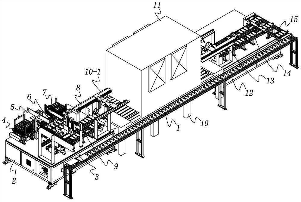
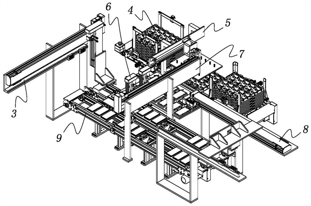
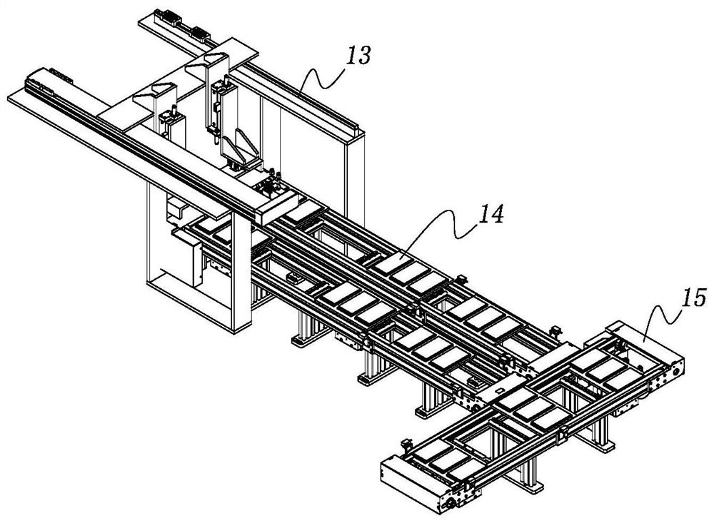
[0039] See figure 1 , The sandblasting processing equipment with automatic loading and unloading functions of the present invention includes a sandblasting support 10 located in the middle, on which a sandblasting device 11 is installed. The front of the sandblasting support 10 is provided with a loading support 2, and the rear is provided with a blanking support 12, and the sides of the sandblasting support 10, the loading support 2 and the blanking support 3 are provided with a Pallet conveyor 1 for conveying pallets 18.

[0040] The sandblasting support 10 supports the sandblasting device 11, the feeding support 2 is used to support the automatic feeding device, the unloading support 12 is used to support the automatic unloading device, and the pallet conveyor 1 is used to support the automatic feeding device. The pallet 18 genera...


PUM


Abstract

The invention relates to sand blasting machining equipment with an automatic feeding and discharging function. The sand blasting machining equipment comprises a sand blasting support located in the middle, a sand blasting device is installed on the sand blasting support, a feeding support is arranged in front of the sand blasting support, a discharging support is arranged behind the sand blasting support, and supporting plate conveyors used for conveying supporting plates are arranged on the side portions of the sand blasting support, the feeding support and the discharging support. A positioning device is arranged in the middle of the feeding support, a feeding conveying device is arranged on the inner side of the positioning device, a tray separating device is arranged on the outer side of the positioning device, a workpiece transferring device is arranged in the middle of the tray separating device, a supporting plate transferring device is arranged on the front portion of the feeding conveying device, a feeding transverse moving device is arranged in the middle of the feeding conveying device, and a feeding longitudinal moving device is arranged on the middle rear portion of the feeding conveying device. A discharging conveying device is installed on the discharging support, a discharging longitudinal moving device is arranged on the middle front portion of the discharging conveying device, and a discharging transverse moving device is arranged at the tail of the discharging conveying device. The sand blasting machining equipment is reasonable in structural design, continuous sand blasting machining is achieved, and the workpiece machining efficiency is improved.

Description

technical field [0001] The invention belongs to the technical field of sandblasting equipment, and in particular relates to a sandblasting processing equipment with automatic loading and unloading functions. Background technique [0002] Sand blasting refers to the process of cleaning and roughening the surface of the substrate by the impact of high-speed sand flow. Compressed air is used as the power to form a high-speed jet beam to spray the spray material (copper ore, quartz sand, corundum, iron sand, Hainan sand, etc.) to the surface of the workpiece to be processed at high speed, so that the appearance or shape of the workpiece surface changes. The impact and cutting effect of the abrasive on the surface of the workpiece makes the surface of the workpiece obtain a certain degree of cleanliness and different roughness, which improves the mechanical properties of the workpiece surface, thus improving the fatigue resistance of the workpiece and increasing the distance betw...

Claims


Application Information

Patent Timeline
Patent Type & Authority Applications(China)
IPC IPC(8): B24C3/00B24C9/00
CPCB24C3/00B24C9/00
Inventor 董梦瑶
Owner CHONGQING IND POLYTECHNIC COLLEGE
Why Eureka
Try Eureka