
Building steel bar machining device

A processing device and technology for building steel bars, applied in the field of building construction, can solve problems such as low safety, low construction efficiency, and high operating intensity, and achieve the effects of improving safety, reducing manual operations, and improving work efficiency

Inactive Publication Date: 2020-08-14
齐嘉蕾
View PDF8 Cites 0 Cited by
  • Summary
  • Abstract
  • Description
  • Claims
  • Application Information

AI Technical Summary

Problems solved by technology

[0002] Steel bars are widely used in building construction, which can increase the stability of buildings. In building construction, because steel bars are generally relatively long, steel bars are often cut and processed during use, and the length of cut steel bars needs to be uniform. Therefore, when cutting and processing steel bars in batches, operators often need to pay attention to the feeding length of steel bars at all times. The operation intensity is relatively high, and workers are prone to fatigue, which will cause accidents. The safety is low and the labor intensity is high. The construction efficiency is low and cannot satisfy the use

Method used


Image

  • Building steel bar machining device
  • Building steel bar machining device
  • Building steel bar machining device

Examples


Embodiment Construction

[0014] All features disclosed in this specification, or steps in all methods or processes disclosed, may be combined in any manner, except for mutually exclusive features and / or steps.

[0015] Combine below Figure 1-Figure 4 The present invention is described in detail, and for convenience of description, the orientations mentioned below are now stipulated as follows: figure 1 The up, down, left, right, front and back directions of the projection relationship itself are the same.

[0016] The present invention relates to a kind of construction reinforcing bar processing device, is mainly used in automobile painting work, the present invention will be further described below in conjunction with accompanying drawing of the present invention:

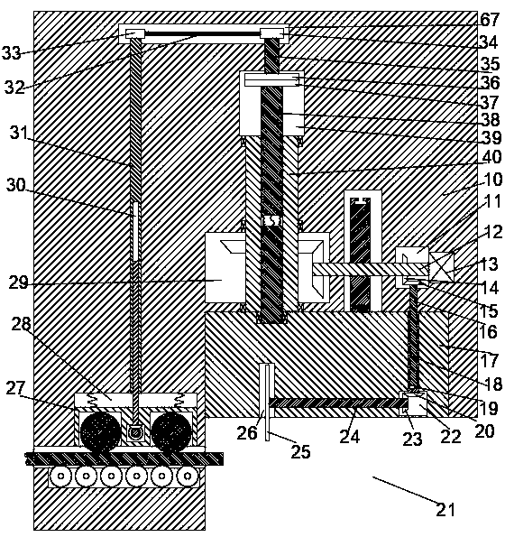
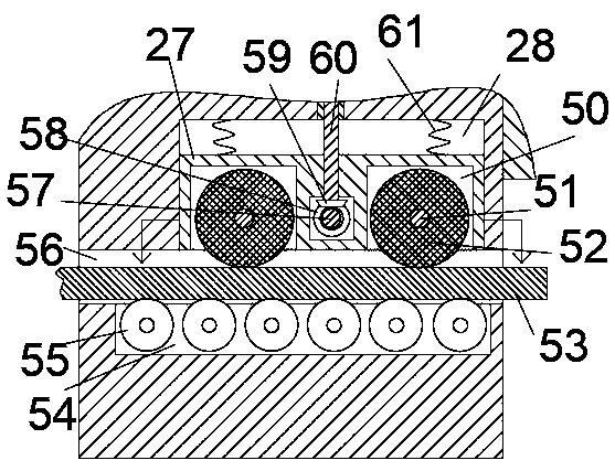
[0017] A construction steel bar processing device according to the present invention comprises a machine body 10, a cutting area 21 is arranged at the lower right part of the machine body 10, a steel bar feeding assembly is arranged on ...


PUM


Abstract

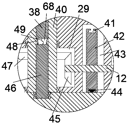
The invention relates to the field of building construction, in particular to a building steel bar machining device. The device comprises a body, wherein a cutting region is formed in the lower rightportion of the body, a steel bar feeding component is arranged at the left side of the cutting region, a cutting component used for cutting steel bars is arranged at the top of the cutting region, thecutting component comprises a lifting groove which communicates with the cutting region, a cutting block is mounted in the lifting groove in a sliding mode, a first rotating cavity is arranged at theright side of the cutting block, a cutting rotary groove provided with a downward opening is arranged at the left side of the first rotating cavity, a first rotary shaft is arranged between the cutting rotary groove and the first rotating cavity in a communicating mode, the left end of the first rotary shaft extends into the cutting rotary groove, and a cutting knife is fixedly mounted at the left end of the first rotary shaft. Through the device, working efficiency is greatly improved, manual operation is reduced, and therefore safety is greatly improved.

Description

technical field [0001] The invention relates to the field of building construction, in particular to a building steel bar processing device. Background technique [0002] Steel bars are widely used in building construction, which can increase the stability of buildings. In building construction, because steel bars are generally relatively long, steel bars are often cut and processed during use, and the length of cut steel bars needs to be uniform. Therefore, when cutting and processing steel bars in batches, operators often need to pay attention to the feed length of steel bars at all times. The operation intensity is relatively high, and workers are prone to fatigue, which will cause accidents. The safety is low and the labor intensity is high. The construction efficiency is low and cannot satisfy the use. Contents of the invention [0003] In view of the above-mentioned technical deficiencies, the present invention proposes a construction steel bar processing device, wh...

Claims


Application Information

Patent Timeline
IPC IPC(8): B21F11/00B21F23/00
CPCB21F11/00B21F23/00
Inventor 齐嘉蕾
Owner 齐嘉蕾
Learn More