Crankshaft machining method

A technology of crankshaft processing and crankshaft, which is applied in the direction of crankshaft, shaft, shaft and bearing, etc., which can solve the problems of low processing efficiency and inability to ensure processing accuracy.

Active Publication Date: 2020-08-14
CHONGQING MEIXIN YINGSHEN MACHINERY CO LTD
View PDF11 Cites 2 Cited by
  • Summary
  • Abstract
  • Description
  • Claims
  • Application Information

AI Technical Summary

Problems solved by technology

However, the crankshaft processed by the above method has low proce

Method used


Image

  • Crankshaft machining method

Examples


Embodiment Construction

[0034] Below in conjunction with accompanying drawing and embodiment the present invention will be further described:

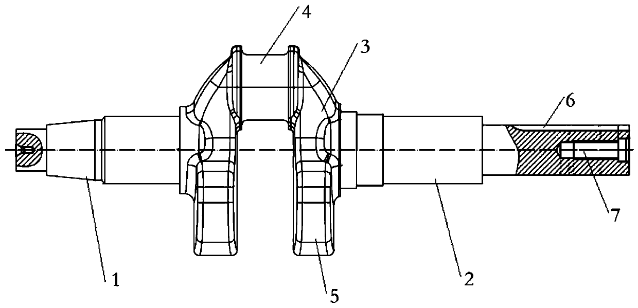
[0035] see figure 1Shown: a crankshaft machining method, including the step of obtaining a crankshaft blank; it is characterized in that it also includes the following steps: a) machining a center hole on the outer end faces of the input shaft section and the output shaft section of the crankshaft; b rough turning and finishing turning Crankshaft input shaft section and rough turning and finishing crankshaft output shaft section; c Turning the inner sides of the two crank arms and the main journal, and making the length dimension of the main journal between the inner surfaces of the two crank arms match the design length dimension; d Machining The keyway of the crankshaft output shaft section and the input shaft section; e quenching the main journal on the crankshaft; f straightening the crankshaft after quenching in step e; g corresponding to the position of...


PUM


Abstract

The invention discloses a crankshaft machining method. The crankshaft machining method comprises the step of acquiring a crankshaft blank, and further comprises the steps of a, conducting machining onthe outer end faces of a crankshaft input shaft section and an output shaft section to obtain center holes; b, conducting rough turning and finish turning on the crankshaft input shaft section and conducting rough turning and finish turning on the crankshaft output shaft section; c, turning the inner sides of two crank arms and a main journal to enable the length of the part, between the inner side faces of the two crank arms, of the main journal to be matched with the designed length; d, machining key grooves of the crankshaft output shaft section and the input shaft section; e, conducting quenching machining on the main journal on a crankshaft; f, conducting straightening treatment on the quenched crankshaft; g, conducting drilling, broaching and tapping at the position corresponding toa center hole of the outer end of the crankshaft output shaft section to obtain a threaded hole; h, conducting thread rolling machining on the small end of the crankshaft input shaft section; and i,conducting grinding machining on the big end of the crankshaft input shaft section and the outer circumferential surface of the big end of the output shaft section. The crankshaft machining method hasthe advantages that the machining efficiency can be improved, and the manufacturing cost can be reduced.

Description

technical field [0001] The invention belongs to the technical field of crankshaft processing, and in particular relates to a crankshaft processing method. Background technique [0002] The crankshaft is the most important component in the engine. It bears the force transmitted by the connecting rod and converts it into torque through the crankshaft output and drives other accessories on the engine to work. The crankshaft is subjected to the joint action of the centrifugal force of the rotating mass, the periodically changing gas inertial force and the reciprocating inertial force, so that the crankshaft is subjected to the bending torsional load. Therefore, the crankshaft is required to have sufficient strength and rigidity, and the surface of the journal needs to be wear-resistant, work evenly, and have good balance. [0003] Such as figure 1 The structure of the crankshaft shown mainly includes left and right input shaft sections 1 and output shaft sections 2 arranged i...

Claims


Application Information

Patent Timeline
IPC IPC(8): B23P15/14
CPCB23P15/14B23P2700/07
Inventor 蔡吉良
Owner CHONGQING MEIXIN YINGSHEN MACHINERY CO LTD
Why Eureka
Try Eureka