A single power source lifting rotating device and production line conveyor belt for production line

A single power source, rotating device technology, applied in the direction of lifting devices, lifting frames, conveyor objects, etc., can solve the problems that the workpiece cannot be turned accurately, the structure of the device is complicated, and the structure is complicated.

Active Publication Date: 2020-12-29
GUANGDONG UNIV OF TECH
View PDF16 Cites 0 Cited by
  • Summary
  • Abstract
  • Description
  • Claims
  • Application Information

AI Technical Summary

Problems solved by technology

At present, the devices that can realize this function are driven by gears or telescopic mechanisms, and the rotation angle is controlled by sensors. Because of the complex structure, it is easy to cause high failure rates, machine failures, and workpieces cannot be turned accurately.
Furthermore, the current devices that can realize this function use dual power sources to achieve lifting and rotating actions, which will also lead to complex structure of the device, and problems such as failures in the cooperative control of dual power sources.

Method used


Image

  • A single power source lifting rotating device and production line conveyor belt for production line
  • A single power source lifting rotating device and production line conveyor belt for production line
  • A single power source lifting rotating device and production line conveyor belt for production line

Examples


Embodiment 1

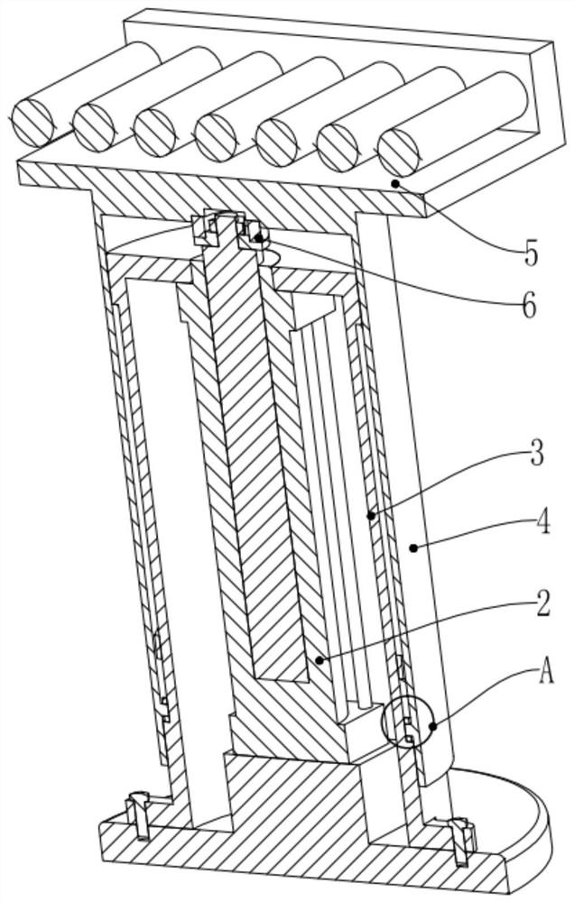
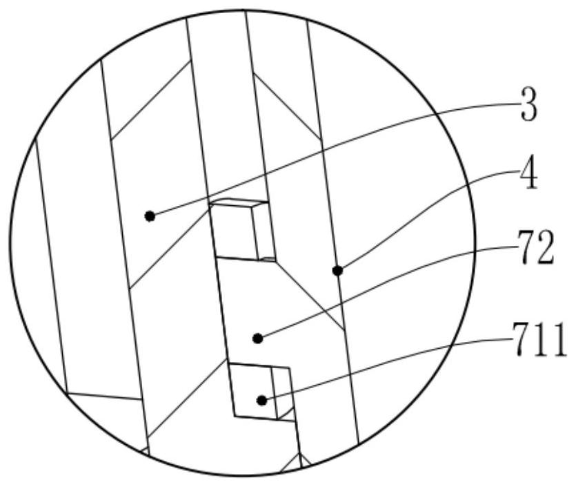
[0067] Such as Figure 6 , the movable cylinder 4 is arranged on the outside of the fixed cylinder 3, the inside of the movable cylinder 4 is provided with a movable part 72, and the outer wall of the fixed cylinder 3 is provided with a guide part 71; Under the guidance of 711, the movable part 72 enters from the lower entrance 76, and rotates a certain angle a along the annular lifting groove 711 (the annular lifting groove 711 is in the side of the columnar fixed cylinder 3, the lower entrance 76 of the annular lifting groove 711 and the upper side The angle formed between the entrances 75 is a) When reaching the upper entrance 75 of the annular lifting groove 711, the transmission device 5 connected to the movable cylinder 4 will also rotate at an angle a synchronously; at the same time, when the movable part 72 enters from the annular lifting groove 711 In the vertical lifting groove 712, under the guiding action of the vertical lifting groove 712 and the reset driving act...

Embodiment 2

[0069] Such as Figure 5 and Figure 7 , the number of mobile slot units is 2; the lower entrance 76 of the annular lift slot 711 in the first mobile slot unit 01 is connected to the lower end 7122 of the vertical lift slot 712 in the second mobile slot unit 02; a single annular lift slot The angle a formed between the lower inlet 76 and the upper inlet 75 of 711 is 180 degrees. The movable cylinder 4 is arranged on the outside of the fixed cylinder 3, the inside of the movable cylinder 4 is provided with a movable part 72, and the outside of the fixed cylinder 3 is provided with a guide part 71; in this embodiment, both the vertical lifting groove and the annular lifting groove 711 are fixed. , the movable part moves relative to both the vertical lift trough and the annular lift trough 711;

[0070] When the vertical driver 2 drives the movable cylinder 4 to rise, under the guiding effect of the annular lifting groove 711, the movable part 72 enters from the lower entrance ...

Embodiment 3

[0080] Based on Embodiment 2, Embodiment 3 is that both the vertical lift groove and the annular lift groove 711 rotate relative to the movable part, and the movable part does not move. The movable cylinder 4 is arranged on the outside of the fixed cylinder 3, the outside of the fixed cylinder 3 is provided with a movable part 72, and the inside of the movable cylinder 4 is provided with a guide part 71; as Figure 8 , the number of mobile slot units is 2; the lower entrance 76 of the annular lift slot 711 in the first mobile slot unit is connected to the lower end 7122 of the vertical lift slot 712 in the second mobile slot unit; the single annular lift slot 711 The angle a formed between the lower inlet 76 and the upper inlet 75 is 180 degrees.

[0081] At the same time, based on Embodiment 2, the movable part 72, the input limiter 73 and the output limiter 74 of the third embodiment are opposite to those of Embodiment 2, as follows:

[0082] In the initial state, the movab...


PUM


Abstract

The invention discloses a single-power-source lifting rotating device for a production line and a production line conveyor belt. The single-power-source lifting rotating device comprises a fixing base, a vertical driver, a fixed cylinder, a movable cylinder, a conveying device and a rotating bearing. A movable part is movably matched with the interior of an annular lifting groove and a vertical lifting groove. The vertical driver drives the movable cylinder to ascend and descend, so that the movable part relatively moves in the annular lifting groove and the vertical lifting groove, the movable cylinder is rotated and lifted, and the conveying device is driven to rotate, ascend and descend. The production line conveyor belt comprises a conveyor belt base and a plurality of single-power-source lifting rotating devices. The single-power-source lifting rotating devices are installed on the conveyor belt base. According to the single-power-source lifting rotating device, the lifting rotating device with a single power source can be formed, a workpiece is rotated by different angles, meanwhile, the conveying function between high and low conveyor belts can be achieved, the structure issimple, the working efficiency is high, and the production efficiency and economic benefits can be greatly improved.

Description

technical field [0001] The invention relates to the technical field of transportation and transportation, in particular to a single power source lifting and rotating device for a production line and a production line conveyor belt. Background technique [0002] In automated industrial production, for some workpieces, the workpiece needs to be turned between the front and rear processes, such as turning 90 degrees, 180 degrees, etc. At present, the usual practice is to lift the workpiece first, then rotate it, and finally turn it The workpiece falls. At present, the devices that can realize this function are driven by gears or telescopic mechanisms, and the rotation angle is controlled by sensors. Because of the complex structure, it is easy to cause high failure rates, machine malfunctions, and workpieces cannot be turned accurately. Furthermore, the current devices that can realize this function use dual power sources to realize lifting and rotating actions, which also lea...

Claims


Application Information

Patent Timeline
Patent Type & Authority Patents(China)
IPC IPC(8): B65G13/06B65G13/12B65G47/24B66F7/10B66F7/28
CPCB65G13/06B65G13/12B65G47/24B66F7/10B66F7/28
Inventor 赖苑鹏刘强赵荣丽冷杰武严都喜林大钦
Owner GUANGDONG UNIV OF TECH
Why Eureka
Try Eureka