Fan rotating speed control method and device and wearing type equipment

A head-mounted device and fan speed technology, which is applied in the field of head-mounted devices and fan speed control, can solve the problems of the fan's actual speed and expected speed error, poor temperature adjustment effect, etc.

Active Publication Date: 2020-08-14
WEIFANG GOERTEK ELECTRONICS CO LTD
View PDF7 Cites 2 Cited by
  • Summary
  • Abstract
  • Description
  • Claims
  • Application Information

AI Technical Summary

Problems solved by technology

When controlling the fan, at present, a PWM (Pulse width modulation, pulse width modulation) signal with a fixed duty ratio is usually output to the fan to control the rotation of the fan, so that the fan rotates according to the desired speed corresponding to the PWM signal, but this This method does not take into account that factors such as the air pressure of the air outlet and air inlet in the head-mounted device have a great influence on the fan speed, which may easily cause a large error between the actual fan speed and the expected speed, and the temperature adjustment effect is poor.

Method used


Image

  • Fan rotating speed control method and device and wearing type equipment
  • Fan rotating speed control method and device and wearing type equipment
  • Fan rotating speed control method and device and wearing type equipment

Examples


Embodiment Construction

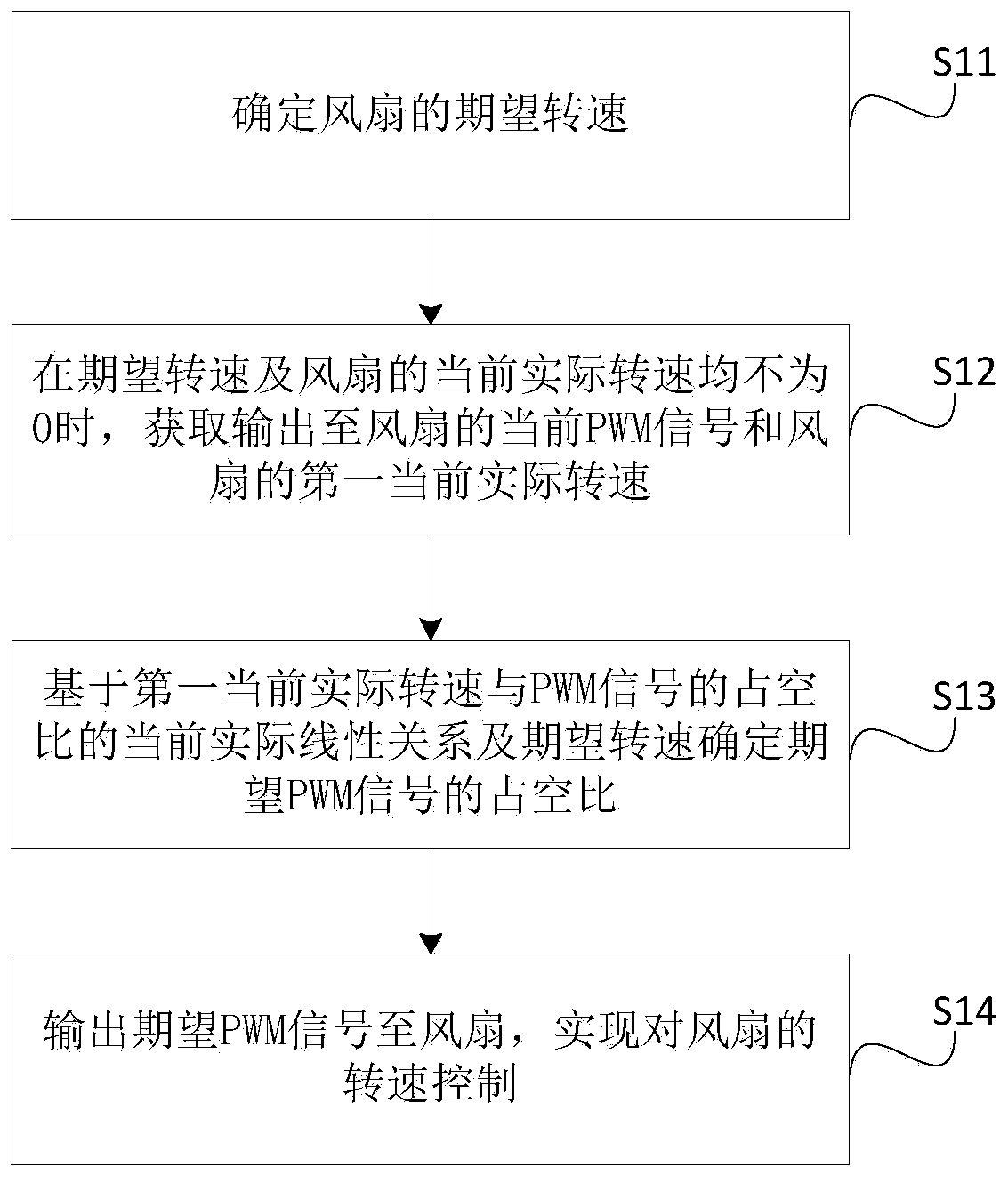
[0037] The core of the present invention is to provide a fan speed control method, device and head-mounted device, which improves the control precision of the fan and has a better temperature adjustment effect.

[0038] In order to make the purpose, technical solutions and advantages of the embodiments of the present invention clearer, the technical solutions in the embodiments of the present invention will be clearly and completely described below in conjunction with the drawings in the embodiments of the present invention. Obviously, the described embodiments It is a part of embodiments of the present invention, but not all embodiments. Based on the embodiments of the present invention, all other embodiments obtained by persons of ordinary skill in the art without making creative efforts belong to the protection scope of the present invention.

[0039] Please refer to figure 1 , figure 1 It is a structural schematic diagram of a fan speed control method provided by the pre...


PUM


Abstract

The invention discloses a fan control method and device and wearing type equipment. After the expected rotating speed of a fan is determined, an expected PWM signal is not determined according to a preset mapping relation between rotating speed and a PWM signal, a current actual linear relation between two can be obtained according to an obtained PWM signal currently output to the fan and the first current actual rotating speed of the fan, then, based on the current actual linear relation and the expected rotating speed, a duty ratio of the expected PWM signal can be obtained, and according tothe expected PWM signal, the fan can be subjected to rotating speed control subsequently. Visibly, a fan control manner considers the influences of factors of an air outlet, an air inlet and the likeof the wearing type equipment on the rotating speed of the fan, through the current actual linear relation between the PWM signal obtained based on the first current actual rotating speed of the fanand the rotating speed, the expected PWM signal is determined, the fan control precision is improved, and the temperature adjusting effect is better.

Description

technical field [0001] The present invention relates to the technical field of wearable device control, in particular to a fan speed control method, device and head-mounted device. Background technique [0002] For head-mounted devices, due to the relatively large workload of calculation and rendering, the system heats up seriously. If the heat is not dissipated in time, it may lead to unstable operation of the system and affect the normal use of the system. As a result, more and more headsets now include built-in fans. When controlling the fan, at present, a PWM (Pulse width modulation, pulse width modulation) signal with a fixed duty ratio is usually output to the fan to control the rotation of the fan, so that the fan rotates according to the desired speed corresponding to the PWM signal, but this This method does not take into account that factors such as the air pressure of the air outlet and air inlet in the head-mounted device have a great influence on the fan speed...

Claims


Application Information

Patent Timeline
Patent Type & Authority Applications(China)
IPC IPC(8): F04D27/00H05K7/20
CPCF04D27/004H05K7/20209Y02B30/70
Inventor 王铁存姜滨迟小羽
Owner WEIFANG GOERTEK ELECTRONICS CO LTD
Why Eureka
Try Eureka