Supercharge Your Innovation With Domain-Expert AI Agents!

Camshaft pin hole expansion measuring pin

A technology for measuring pins and camshafts, used in measuring devices, mechanical measuring devices, mechanical diameter measurement, etc., can solve the problems of unstable installation of measuring pins, inclination of measuring pins, poor measurement accuracy of measuring pins, etc., so as to improve accurate auxiliary measurement. effect, improve stability, reduce wear effect

Inactive Publication Date: 2020-08-14
焦艳新
View PDF0 Cites 1 Cited by
  • Summary
  • Abstract
  • Description
  • Claims
  • Application Information

AI Technical Summary

Problems solved by technology

[0005] In order to make up for the deficiencies in the prior art, the present invention proposes a camshaft pin hole expansion measuring pin. The present invention is mainly used to solve the problem that the existing measuring pin needs to measure the diameter of the pin hole when the diameter of the pin hole is relatively large. , so as to realize that the cylinder can be applied to pin holes of different sizes, and this kind of measuring pin is due to the point contact between the internal steel ball and the inner wall of the pin hole, which will easily cause the installation of the measuring pin in the pin hole to be unstable, and at the same time easily lead to measurement The phenomenon that the pin is inclined, which in turn affects the poor measurement accuracy of the measuring pin

Method used


Image

  • Camshaft pin hole expansion measuring pin
  • Camshaft pin hole expansion measuring pin
  • Camshaft pin hole expansion measuring pin

Examples


Embodiment approach

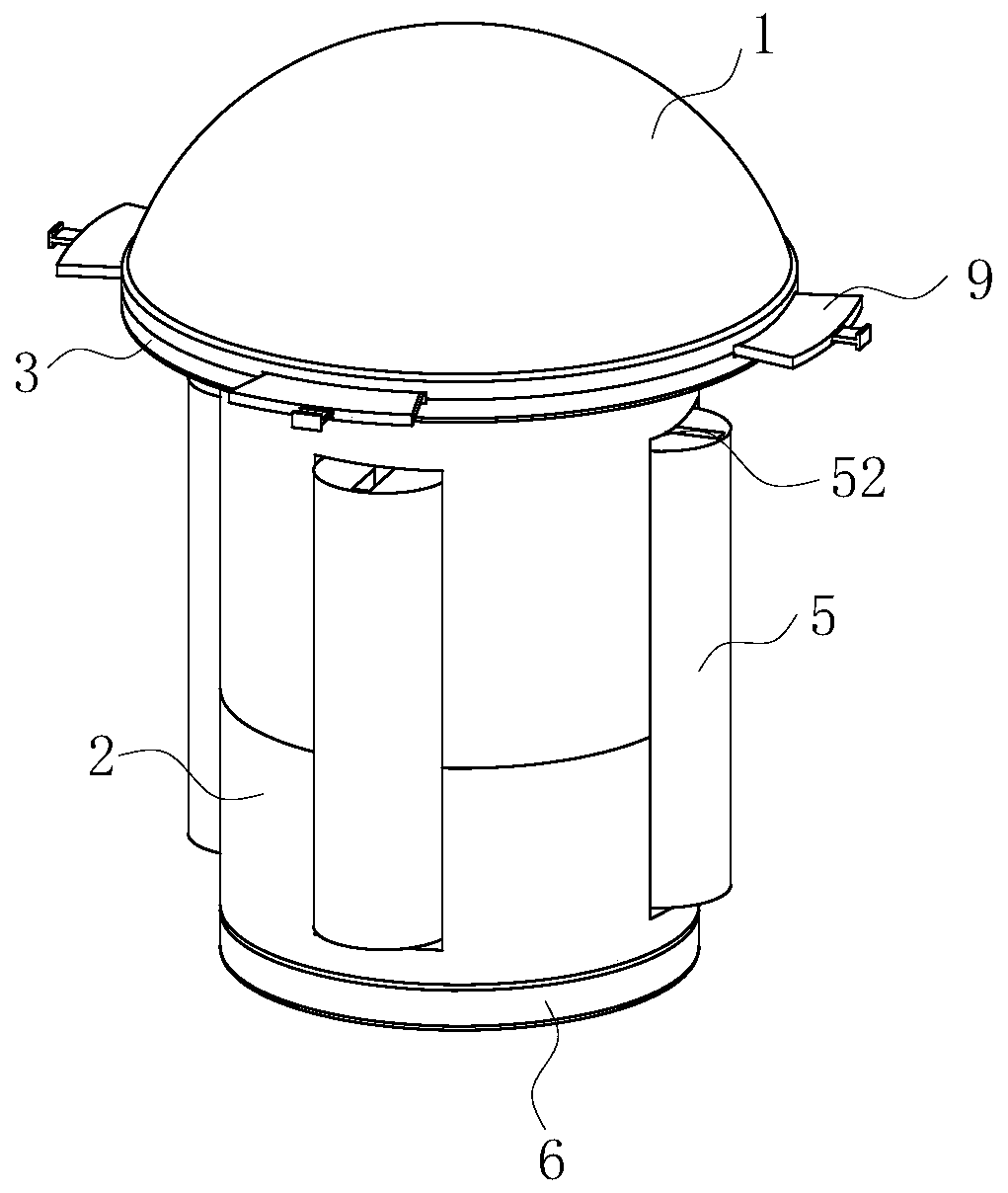
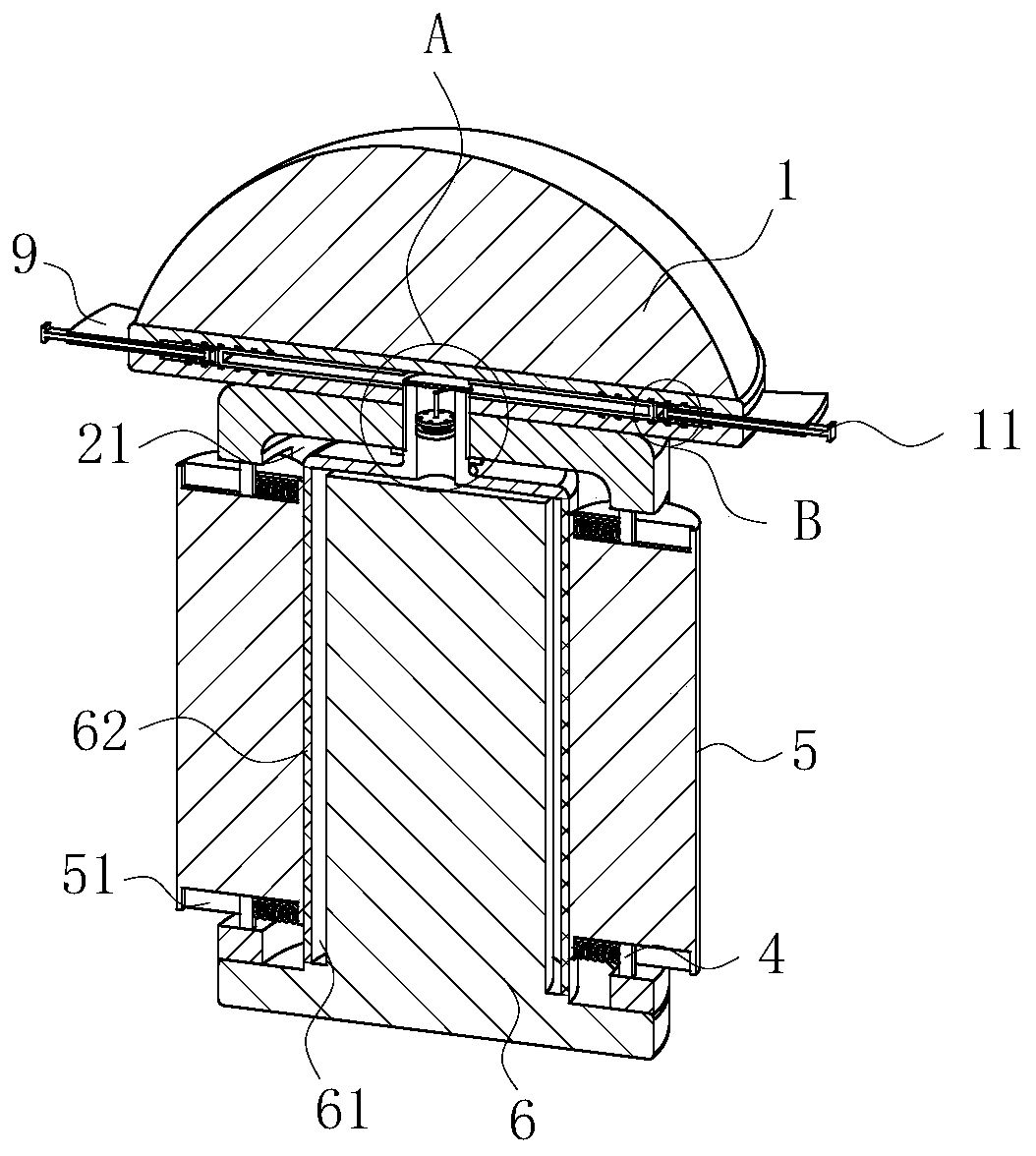
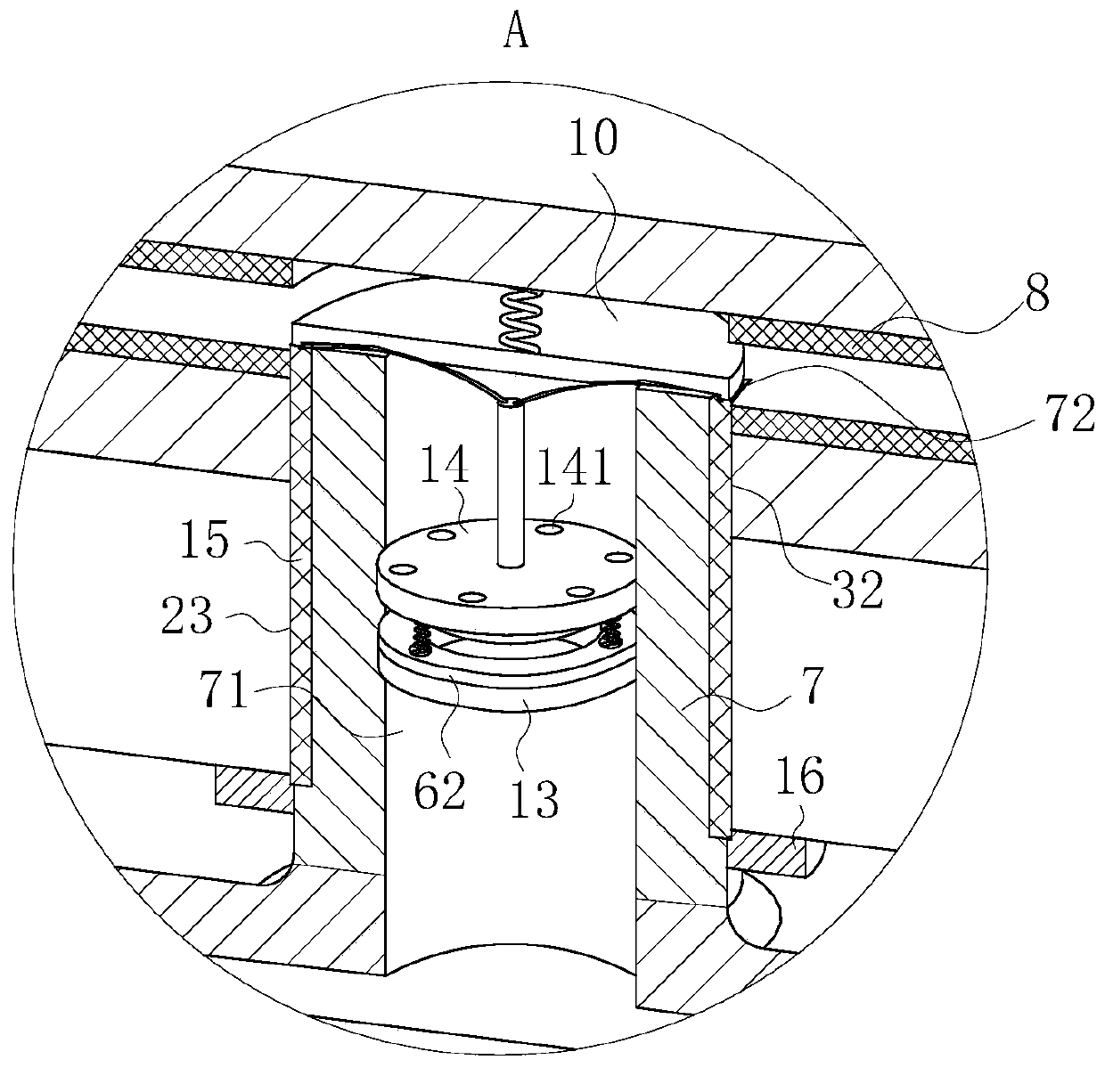
[0025] As an embodiment of the present invention, an expansion cavity 61 is opened on the outer wall of the extruding column 6, and the outer wall of the expansion cavity 61 is an elastic layer 62; the inside of the threaded column 7 is provided with a diversion cavity 71, And the diversion chamber 71 communicates with the expansion chamber 61; the inside of the limiting disc 3 is provided with a liquid chamber 31, and the liquid chamber 31 is filled with liquid through the elastic membrane 8; the side wall of the liquid chamber 31 is provided with a drainage hole 32 , and the drainage hole 32 communicates with the threaded hole 23; the outer ring wall of the liquid chamber 31 is evenly slid to arrange the squeeze strip 9, and the cross section of the squeeze strip 9 is a T-shaped structure; one end of the squeeze strip 9 is connected to the The outer wall of the elastic film 8 is connected, and the other end of the extrusion strip 9 is located outside the limit plate 3; during...


PUM


Abstract

The invention belongs to the technical field of camshaft pin hole measurement, and particularly relates to a camshaft pin hole expansion measuring pin. The camshaft pin hole expansion measuring pin comprises a measuring pin head and a measuring column, wherein one end part of the measuring column is connected with the measuring pin head through a limiting disc, and an insertion cavity is formed inthe other end of the measuring column; sliding cavities are uniformly formed in the circumferential outer wall of the measuring column; limiting blocks are arranged on the inner walls of the two endsof each sliding cavity, and positioning columns are slidably arranged in the sliding cavities; limiting grooves are formed in the outer walls of the two ends of each positioning column, limiting blocks are slidably arranged in the limiting grooves through springs, and the springs are located in the measuring column; an extrusion column is inserted and extruded in the insertion cavity, and one endpart of the extrusion column is in threaded connection into a threaded hole through a threaded column; and the extrusion column is in extrusion contact with a plurality of positioning columns arranged on the measuring column in a sliding manner, and the other end part of the extrusion column is located outside the measuring column. The measurement stability and accuracy of the measuring pin improved, the insertion stability of the measuring pin in the pin hole is improved at the same time.

Description

technical field [0001] The invention belongs to the technical field of camshaft pin hole measurement, in particular to a camshaft pin hole expansion measuring pin. Background technique [0002] When using ADCOLE to measure the camshaft, in order to determine the phase angle relationship between the camshaft pin hole and the cam, a measuring pin is needed to assist in measuring the center position of the pin hole. [0003] The Chinese patent discloses a camshaft pin hole expansion measuring pin. The patent application number is 2014207768347. The main feature is that the measuring pin body is a hole in the axial direction, and the cylinder wall perpendicular to the axial direction has a through hole communicating with the hole. Steel balls are placed in the two through holes, wedge-shaped blocks are respectively placed in the holes on both sides of the two steel balls, and a spring is arranged between the wedge-shaped blocks close to the port of the cylinder and the seal of t...

Claims


Application Information

Patent Timeline
Patent Type & Authority Applications(China)
IPC IPC(8): G01B5/00G01B5/12
CPCG01B5/00G01B5/12
Inventor 焦艳新高四新
Owner 焦艳新
Features
  • R&D
  • Intellectual Property
  • Life Sciences
  • Materials
  • Tech Scout
  • Unparalleled Data Quality
  • Higher Quality Content
  • 60% Fewer Hallucinations
Learn More