
IoT-based cable monitoring system

A monitoring system, the technology of the Internet of Things, applied in the field of cables, can solve the problems of fire, explosion, and inaccurate data collection, and achieve the effect of noise reduction.

Active Publication Date: 2020-12-08
JIANGSU ELECTRIC POWER CO
View PDF15 Cites 0 Cited by
  • Summary
  • Abstract
  • Description
  • Claims
  • Application Information

AI Technical Summary

Problems solved by technology

[0002] Most of the cable failures are caused by problems at the cable joints. Serious situations such as fires and explosions occur under the condition of continuous energy accumulation, threatening personal and property safety, especially at the cross-linked cable joints, which have high carrying voltage and current carrying capacity Strong, high current density, higher sealing performance and insulation level should be maintained. In order to monitor the information at the cable joint in real time, insulation detection devices (such as insulation detection sensors, insulation testers, insulation resistance tester) to detect the insulation signal, the displacement sensor detects the gap at the cable joint, the current transformer detects the current carrying capacity at the cable joint, and the temperature sensor detects the temperature signal at the cable joint, and then connects to the intelligent controller. Network transmission to the automation master station for monitoring, but due to the influence of external interference signal coupling, noise and other random interference when the insulation detection device detects and transmits to the intelligent controller, when the detected insulation signal deviates from the normal value, it is not clear to detect Whether the insulation signal is affected by interference or the insulation fault at the cable joint will cause the collected data to be inaccurate, so it is necessary to reduce the noise and handle the abnormality of the insulation signal

Method used


Image

  • IoT-based cable monitoring system

Examples


Embodiment Construction

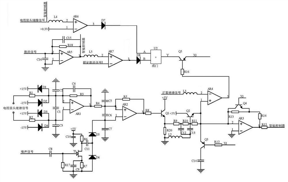
[0008] Regarding the aforementioned and other technical contents, features and effects of the present invention, refer to the appended figure 1 It will be apparent from the detailed description of the embodiments. The structural contents mentioned in the following embodiments are all based on the accompanying drawings of the description.

[0009] Exemplary embodiments of the present invention will be described below with reference to the accompanying drawings.

[0010] The cable monitoring system based on the Internet of Things includes a cable joint data acquisition module, an intelligent controller, and an automation master station. The cable joint data acquisition module transmits the collected cable joint information to the intelligent controller. The cable joint data acquisition module includes a cable joint gap detection module, an ampacity detection module, and an insulation detection module. The dynamic filter receives the cable joint insulation signal detected by th...


PUM


Abstract

The invention discloses a cable monitoring system based on the Internet of Things. An insulation signal detected by an insulation detection module receives a cable joint insulation signal detected bya sensor through a preprocessor by means of amplitude limiting and a first differential filter, the signals enter a second differential filter and are counteracted with noise signals to realize noisereduction processing, wherein the noise signals are detected and output by the noise sensor, obtained by amplification of an amplifying circuit and half-wave rectification, and then subjected to buffering to filter out an abnormal high value; whether the cable joint insulation signal is abnormal or not is judged, the cable joint insulation signal is released to the ground when being abnormal, andthe cable joint insulation signal is subjected to amplitude-limiting amplification and then output when being normal, that is, the cable joint insulation signal is transmitted to an intelligent controller after being subjected to anomaly processing. Whether the cable joint mechanical abnormal information detected by a cable joint gap detection module or the current-carrying capacity information, which is detected by a current-carrying capacity detection module, of the cable joint is abnormal or not is the basis for judging whether the cable joint insulation signal is abnormal or not, and the insulation detection precision is improved.

Description

technical field [0001] The invention relates to the technical field of cables, in particular to a cable monitoring system based on the Internet of Things. Background technique [0002] Most of the cable failures are caused by problems at the cable joints. Serious situations such as fires and explosions occur under the condition of continuous energy accumulation, threatening personal and property safety, especially at the cross-linked cable joints, which have high carrying voltage and current carrying capacity Strong, high current density, higher sealing performance and insulation level should be maintained. In order to monitor the information at the cable joint in real time, insulation detection devices (such as insulation detection sensors, insulation testers, insulation resistance tester) to detect the insulation signal, the displacement sensor detects the gap at the cable joint, the current transformer detects the current carrying capacity at the cable joint, and the temp...

Claims


Application Information

Patent Timeline
Patent Type & Authority Patents(China)
IPC IPC(8): G01R31/12
CPCG01R31/1272
Inventor 刘莹雪
Owner JIANGSU ELECTRIC POWER CO
Learn More