
Coaxial connector

A technology of coaxial connector and shaft center, which is applied in the direction of connection, connection part installation, two-part connection device, etc., can solve the problem of coaxial connector voltage standing wave ratio deterioration, and achieve the effect of preventing position deviation

Inactive Publication Date: 2020-08-14
FUJIKURA LTD
View PDF7 Cites 0 Cited by
  • Summary
  • Abstract
  • Description
  • Claims
  • Application Information

AI Technical Summary

Problems solved by technology

[0005] However, in recent years, the amount of information handled by electronic devices has increased, and along with this, the data transmission speed between substrates has also increased dramatically. In coaxial connectors that handle high-frequency signal transmission, even tiny The deviation of the installation position will also lead to the deterioration of the voltage standing wave ratio of the coaxial connector

Method used


Image

  • Coaxial connector
  • Coaxial connector
  • Coaxial connector

Examples


Embodiment

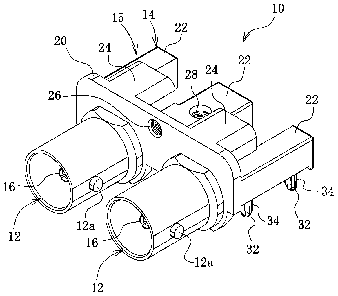
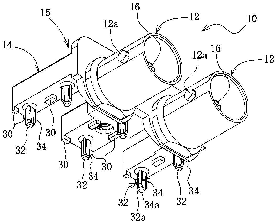
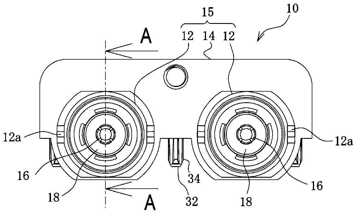
[0079] Made with Figure 1 to Figure 8 A sample (example) of a coaxial connector having the structure shown, and a sample of a coaxial connector (not shown) having the same structure as the coaxial connector of the example except that no protrusion is provided on the mounting leg (Comparative example), the voltage standing wave ratio was measured using the network analyzer. show the result in Figure 11 .

[0080] Figure 11 In , the horizontal axis represents frequency (GHz), and the vertical axis represents voltage standing wave ratio. The characteristic curve drawn by the solid line in the figure shows the frequency characteristic of the voltage standing wave ratio of the coaxial connector of the example, and the characteristic curve drawn by the dotted line shows the frequency characteristic of the voltage standing wave ratio of the coaxial connector of the comparative example.

[0081] From these results, it can be seen that, in the sample of the present invention, th...


PUM


Abstract

To provide a coaxial connector capable of preventing an increase in voltage standing wave ratio due to misalignment of a coaxial connector at the time of mounting of the coaxial connector on a board.A coaxial connector 10 includes a center contact 16, an insulator 18 that holds the center contact 16, and an external conductor 15 including an external contact 12 that holds an insulator 18 and is coupled to a mating connector and a base 14 on which a mounting leg 32 inserted into a through holes of a board is formed. The mounting leg 32 has at least two protrusions 34 that are spaced apart fromeach other in a plane perpendicular to the axis.

Description

[0001] This application is a divisional application, the application number of the parent case: 201810199123.0, the application date: March 12, 2018, the name of the invention: coaxial connector. technical field [0002] The present invention relates to a coaxial connector used in electronic equipment such as a communication card, mobile communication equipment, audio equipment, video equipment, etc., especially a coaxial connector mounted on a substrate and used. Background technique [0003] As such a coaxial connector, the following is known in Patent Document 1, which includes: a center contact; an insulator that holds the center contact; and an outer conductor that holds the insulator and is coupled to the opposite side for connection The fitting part of the device, and the mounting part mounted on the substrate. [0004] In the mounting part, there is a cylindrical mounting foot that is inserted into the through hole of the substrate and soldered. In order to ensure th...

Claims


Application Information

Patent Timeline
Patent Type & Authority Applications(China)
IPC IPC(8): H01R24/38H01R13/73H01R12/71
CPCH01R12/716H01R13/73H01R24/38
Inventor 仙波信行
Owner FUJIKURA LTD
Learn More