Electric power fitting applied to overhead line

A technology for power fittings and overhead lines, which is used in overhead installation, electrical components, cable installation, etc., can solve problems such as damage at the connection between cables and fittings, lack of buffer unloading force, short-circuiting of adjacent cables, etc., to reduce power failures , Improve the scope of application and prevent the effect of cable contact

Active Publication Date: 2020-08-14
SHANDONG LUNENG GUANGDA ELECTRIC POWER EQUIP
View PDF7 Cites 5 Cited by
  • Summary
  • Abstract
  • Description
  • Claims
  • Application Information

AI Technical Summary

Problems solved by technology

[0004] The purpose of the present invention is to solve the problem that the traditional spacer fittings in the prior art do not have the function of buffering and unloading force, the connection between the cable and the fittings is damaged or even broken due to the cutting force, and the spacer fittings are also easy to use due to their excessive rigidity lead to its breakage, resulting in the short circuit fault caused by the contact of adjacent cables, and a kind of power fittings applied to overhead lines is proposed

Method used


Image

  • Electric power fitting applied to overhead line
  • Electric power fitting applied to overhead line
  • Electric power fitting applied to overhead line

Examples


Embodiment 1

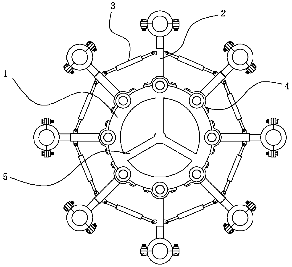
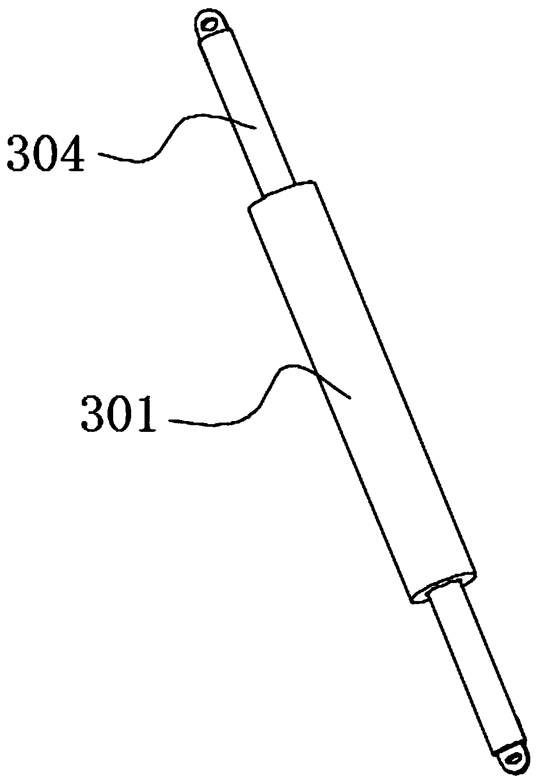
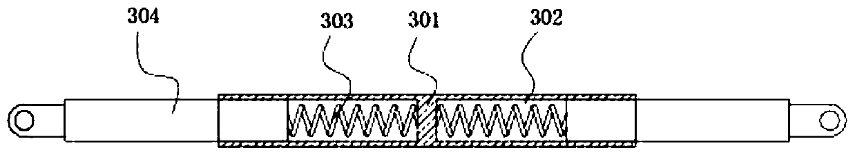
[0058] refer to Figure 1-10 , including a support ring body 1, a rotating support assembly 2 and an interval buffer assembly 3, a reinforcing support frame 5 is fixedly arranged in the middle of the support ring body 1, and an interval buffer assembly 3 is installed between two rotation support assemblies 2 through rotation pins , the interval buffer assembly 3 separates the adjacent rotating support assemblies 2 and performs windproof buffering and unloading force through elastic expansion and contraction.

[0059] The rotating support assembly 2 includes a rotating base, an elastic telescopic pole 201 and a holding hoop, the rotating base is rotatably mounted on the side wall of the support ring body 1, the holding hoop is fixedly arranged on the upper end of the elastic telescopic pole 201, and the rotating base is provided with a Screw hole 3 207 is arranged, and the lower end of elastic telescopic pole 201 is fixedly provided with bolt 205, and the lower end of elastic t...

Embodiment 2

[0068] refer to Figure 1-11 In this embodiment, the structural design of the support ring body 1 and the spacer buffer assembly 3 is the same as that of the first embodiment, except that the structure of the rotating support assembly 2 is different. In this embodiment, the rotating base includes a rotating shaft 206 and fixed ends at both ends. The connected limiting disc 208 and the rotating shaft 206 are rotatably mounted on the side wall of the supporting ring body 1 . In this embodiment, when the rotating support assembly 2 is assembled, the rotating shaft 206 is directly placed in the semi-arc rotating groove 101, and the locking member 4 is locked in the semi-arc through the screw through the first screw hole 102 and the second screw hole 405. At the position of the circular rotation groove 101, the semi-arc-shaped limiting groove 404 on the locking member 4 and the semi-arc-shaped rotating groove 101 on the support ring body 1 together form a complete annular limiting ...

Embodiment 3

[0070] refer to Figure 1-5 , 12 and 13, the structural design of the space buffer assembly 3 in this embodiment is the same as that of the rotating support assembly 2 in Embodiment 1, the difference is that the structure of the support ring 1 in this embodiment is different, in this embodiment, The outer wall of the supporting ring body 1 is equidistantly provided with integral rotating rings 103 , and the outer wall of the rotating ring 103 is provided with an arc-shaped notch 104 , and the rotating shaft 206 rotates in the arc-shaped notch 104 .

[0071] In this embodiment, the rotating shaft 206 is passed through the rotating ring 103, and then the bolt 205 at the lower end of the elastic telescopic strut 201 is passed through the arc-shaped notch 104 and screwed into the screw hole 3 207 on the rotating shaft 206, and at the same time the bolt is The perforation 209 on the 205 is located on the same straight line as the channel 211, and then the stop bar 212 is passed thr...


PUM


Abstract

The invention discloses an electric power fitting applied to an overhead line, relating to the field of electric power fittings. The electric power fitting comprises a supporting ring body, rotary supporting assemblies and spacing buffering assemblies. The lower ends of the rotary supporting assemblies are detachably and rotationally installed on the side walls of the supporting ring body. Detachable holding hoops are fixedly arranged at the upper ends of the rotating supporting assemblies, a spacing buffer assembly is rotationally installed between every two rotating supporting assemblies through a rotating pin, and the spacing buffer assemblies separate the adjacent rotating supporting assemblies and conduct windproof buffer force unloading through elastic stretching and retracting. Thenumber of the rotary supporting assemblies can be flexibly adjusted according to the number of overhead line cables, and the spacing installation requirements of various overhead lines are met; the spacing buffer assemblies and the rotating support assemblies can guarantee enough support spacing strength and can perform small-range rotation and elastic buffer force unloading at the same time, therefore, the spacing fittings and power cables are protected, power faults are reduced, and the electric power fitting is suitable for popularization and application.

Description

technical field [0001] The invention relates to the field of electric fittings, in particular to electric fittings applied to overhead lines. Background technique [0002] Power fittings are metal accessories that connect and combine various devices in the power system to transmit mechanical loads, electrical loads and some kind of protection. Iron or aluminum metal accessories widely used in transmission lines are collectively referred to as fittings. There are many types of fittings with different uses, for example, various clamps for installing wires, various hanging rings for forming insulator strings, various crimping tubes and repair tubes for connecting wires, and various types of spacers for splitting wires In addition, there are various types of wire fittings used for poles and towers, as well as the size of the protective wires, which must cooperate with each other. [0003] In overhead lines, it is often necessary to connect overhead and install multiple sets of...

Claims


Application Information

Patent Timeline
Patent Type & Authority Applications(China)
IPC IPC(8): H02G7/12H02G7/14
CPCH02G7/125
Inventor 刘杰
Owner SHANDONG LUNENG GUANGDA ELECTRIC POWER EQUIP
Why Eureka
Try Eureka