Switching circuit for controlling clutch and brake of loom and working method of switching circuit

A switching circuit, clutch control technology, applied in general control systems, looms, program control and other directions, can solve the problems affecting the quality of weaving, can not be disconnected in time, slow starting speed, etc., to improve the efficiency of weaving, improve weaving. The effect of cloth quality and fast startup speed

Pending Publication Date: 2020-08-14
NANTONG VOCATIONAL COLLEGE
View PDF0 Cites 1 Cited by
  • Summary
  • Abstract
  • Description
  • Claims
  • Application Information

AI Technical Summary

Problems solved by technology

Although the circuit has a good circuit protection function, due to the residual magnetism of the materials used in the production of brakes and clutches, it cannot be disengaged in time.
[0003] In actual operation, there are often phenomena such as slow starting speed and insensitive inching, which seriously affect the quality of weaving. Even when starting, the clutch pulls in and the motor runs, but the brake is still braked due to the residual magnetism of the brake, causing the belt to break.

Method used


Image

  • Switching circuit for controlling clutch and brake of loom and working method of switching circuit
  • Switching circuit for controlling clutch and brake of loom and working method of switching circuit
  • Switching circuit for controlling clutch and brake of loom and working method of switching circuit

Examples


Embodiment Construction

[0035] In order to make the technical problems, technical solutions and advantages to be solved by the present invention clearer, the following will describe in detail with reference to the drawings and specific embodiments.

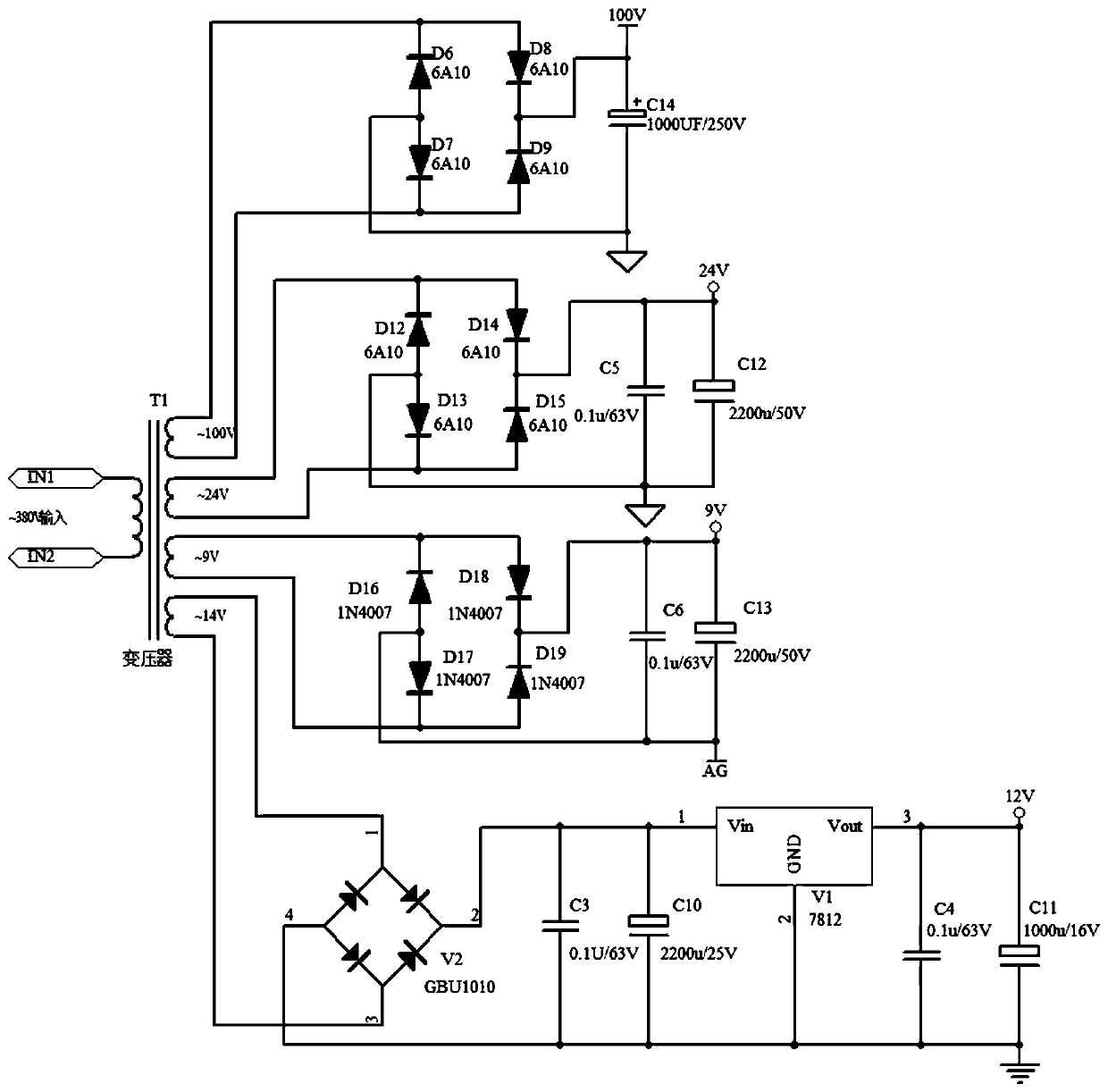
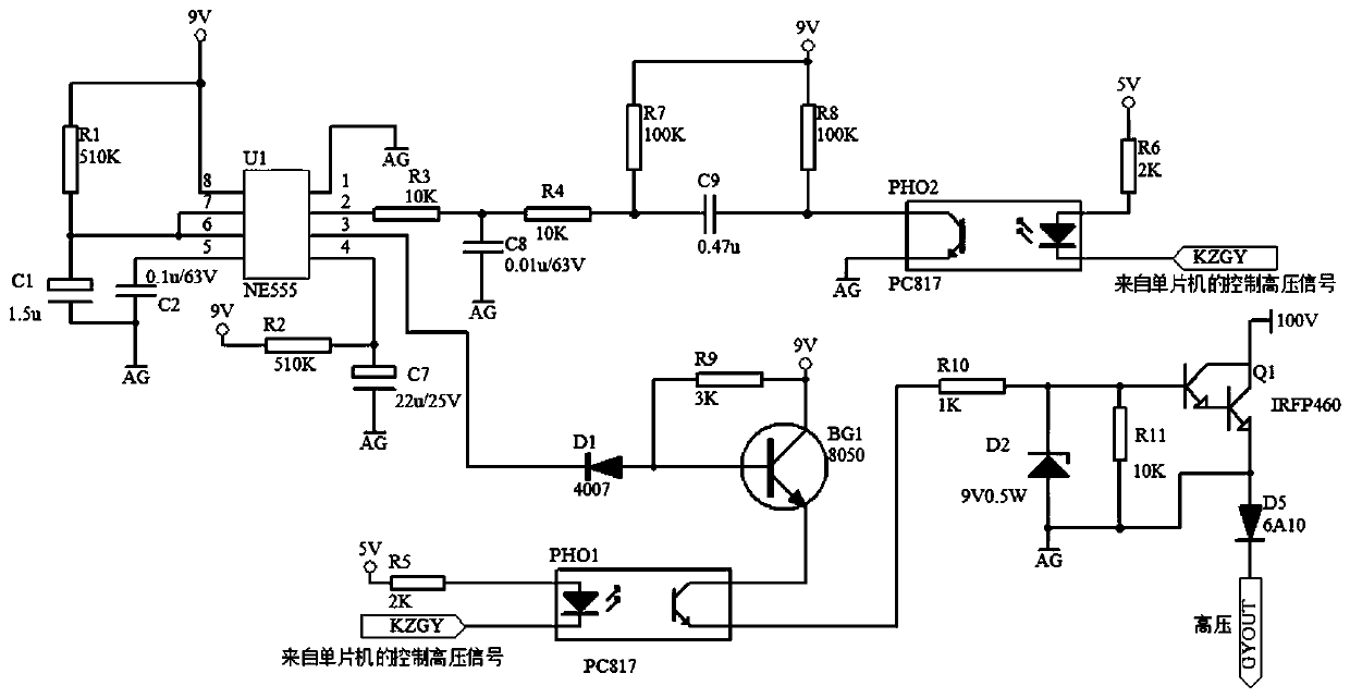
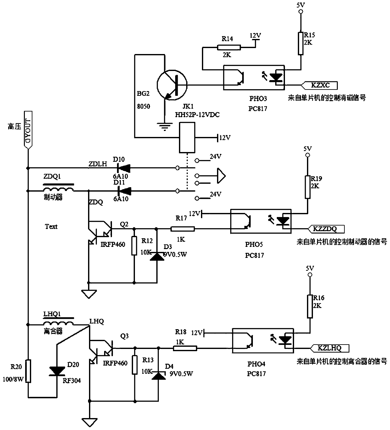
[0036] like figure 1 , figure 2 and image 3 As shown, a switching circuit for controlling the clutch and brake of the loom includes a power supply circuit, a high-voltage control circuit, a brake clutch control circuit and a single-chip microcomputer.

[0037] The power supply circuit includes a transformer, a plurality of rectification circuits, a plurality of filter circuits and a voltage stabilizing circuit; the primary winding end of the transformer is 380V alternating current, and the secondary winding end is respectively 100V alternating current, 24V alternating current, 9V alternating current, and 14V alternating current The multiple rectification circuits and filter circuits are respectively used to rectify and filter DC 100V, 24V, 9V and 12V...


PUM


Abstract

The invention provides a switching circuit for controlling a clutch and a brake of a loom. The switching circuit comprises a power supply circuit, a high-voltage control circuit, a brake and clutch control circuit and a single chip microcomputer; the power supply circuit comprises a transformer, a rectifying circuit, a filtering circuit and a voltage stabilizing circuit; the output end of the single chip microcomputer outputs KZGY, KZXC, KZZDQ and KZLHQ signals; the high-voltage control circuit provides 100V direct-current high voltage for the brake and clutch control circuit, and the brake and clutch control circuit comprises a demagnetization loop, a brake control loop and a clutch control loop. The invention further provides a working method of the switching circuit for controlling theclutch and the brake of the loom. The working method comprises the following steps: working of the power supply circuit, working of the high-voltage control circuit, realization of a demagnetization function, realization of a clutch function and realization of a brake function. According to the invention, the effects of high starting speed and inching sensitivity of the loom can be realized, and the weaving quality and the weaving efficiency can be improved.

Description

technical field [0001] The invention belongs to the technical field of loom control, and relates to a control circuit of a loom, in particular to a switching circuit for controlling a clutch and a brake of a loom and a working method thereof. Background technique [0002] In the loom control system, the conventional protection circuit of the brake and clutch control circuit is a release current circuit composed of reverse connection diodes and a resistor at the two ends of the brake and clutch. Although the circuit has a good circuit protection function, due to the residual magnetism of the materials used in the current brake and clutch production, it cannot be disengaged in time. [0003] In actual operation, slow starting speed and insensitive inching often occur, seriously affecting the quality of weaving. Even when starting, the clutch pulls in and the motor runs, but the brake is still braked due to the residual magnetism of the brake, causing the belt to break. Conte...

Claims


Application Information

Patent Timeline
Patent Type & Authority Applications(China)
IPC IPC(8): H02M7/06D03D51/00G05B19/042
CPCD03D51/00G05B19/042H02M7/06H02M1/36
Inventor 严周鹏刘卓魁曹娇娇于君丁一诺陈卫兵束慧
Owner NANTONG VOCATIONAL COLLEGE
Why Eureka
Try Eureka