
Apparatus and method for heating a device for exhaust gas after-treatment

A technology of exhaust post-treatment and heating method, which is applied in the direction of electric control of exhaust treatment device, diagnostic device of exhaust treatment device, exhaust device, etc., and can solve the problems of undisclosed targeted improvement of equipment and methods , to achieve the effect of reducing exhaust emissions

Active Publication Date: 2020-08-14
VTESCO TECH GMBH
View PDF19 Cites 0 Cited by
  • Summary
  • Abstract
  • Description
  • Claims
  • Application Information

AI Technical Summary

Problems solved by technology

So far, the prior art has not disclosed any devices and methods to improve these problems in a targeted manner

Method used


Image

  • Apparatus and method for heating a device for exhaust gas after-treatment
  • Apparatus and method for heating a device for exhaust gas after-treatment

Examples


Embodiment Construction

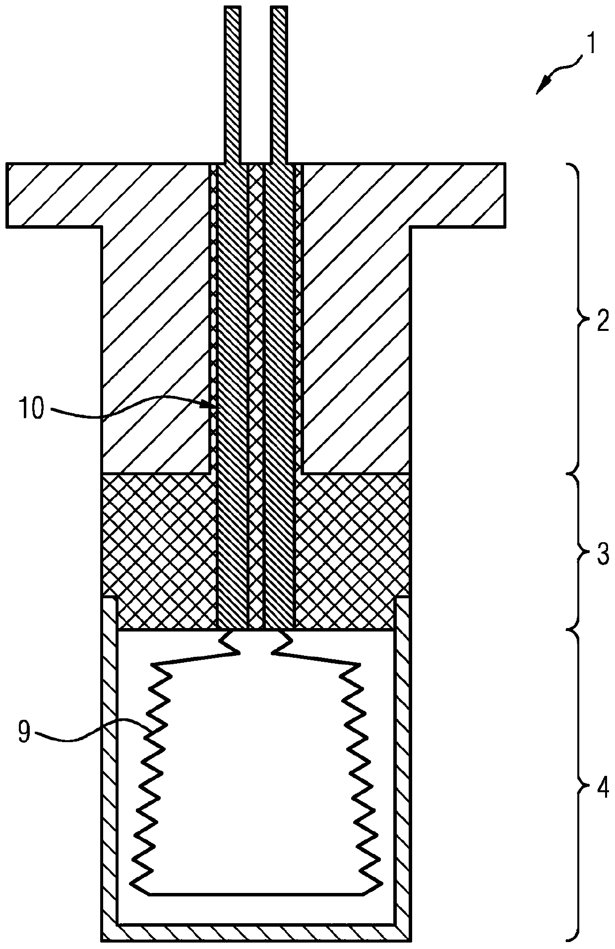
[0036] figure 1 A schematic sectional illustration through the heating element 1 is shown. The heating element 1 is divided into three zones. The "cold" end 2 forms the installation area of ​​the heating element 1 . Via this region 2 the heating element 1 can be fastened to the shell of the honeycomb body and thus positioned in the hollow of the honeycomb body.

[0037] Below this zone, zone 3 represents the insulation zone, which creates thermal insulation between the heating zone 4 (to be described below) and the installation zone 2 . The heating zone 4 can also be referred to as a heating zone.

[0038] The entire heating element 1 is of pin-shaped design and can preferably be inserted into the honeycomb body in the radial direction. The insulating region 3 reduces the heat released by the heating element 1 towards the installation region 2 , so that at the same time the heat loss to the installation region 2 and thus to the outside of the honeycomb body is also reduced...


PUM


Abstract

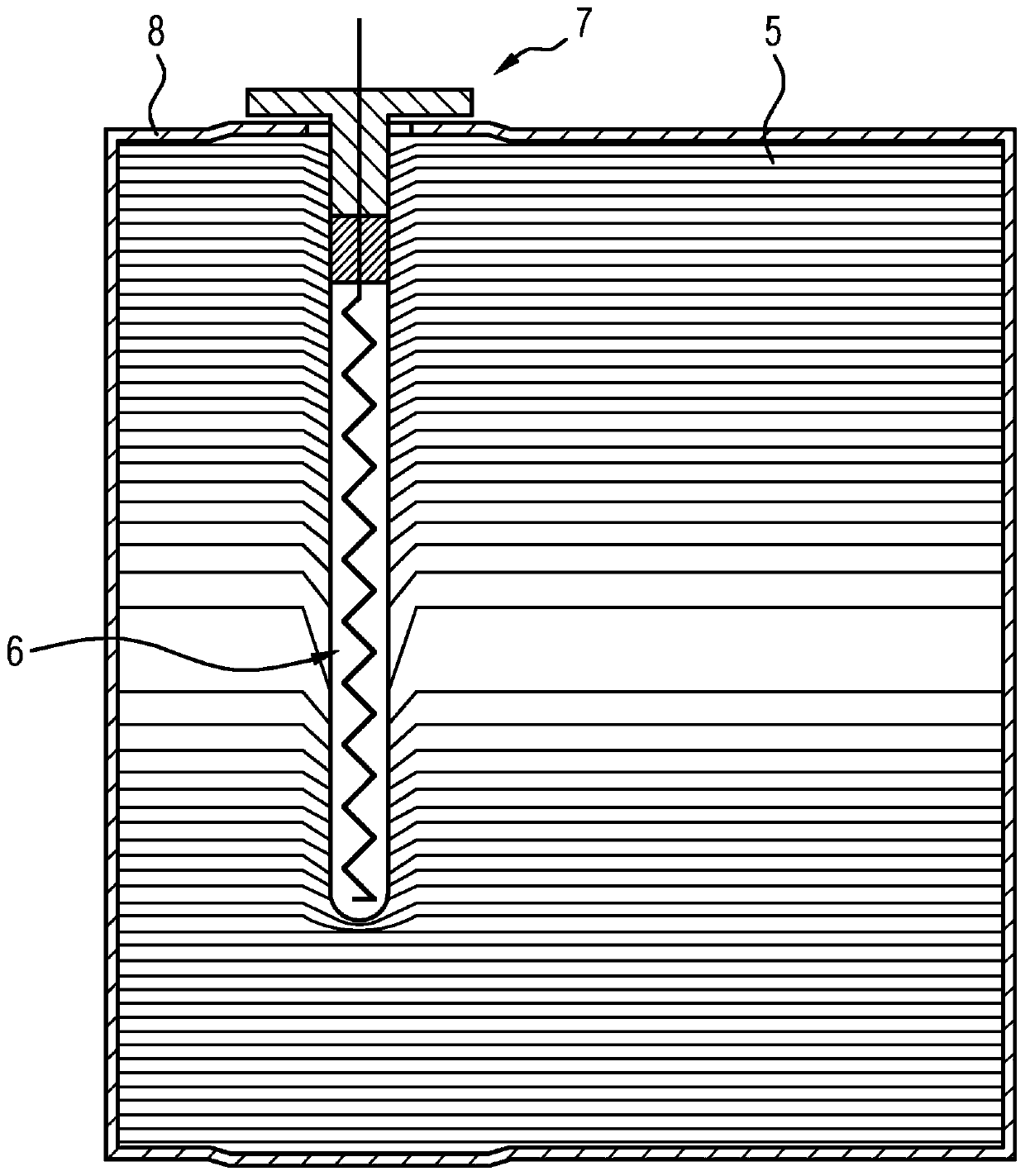
The invention relates to a device for heating an exhaust gas after-treatment unit in a vehicle which, besides a combustion engine, also comprises an electric motor as a drive source, wherein at leastone electric heating element (1, 7) is provided, which, in order to heat a honeycomb body (5) through which exhaust gas can flow, is arranged in a cavity (6) formed in the honeycomb body (5), whereinthe honeycomb body (5) is formed from a plurality of metal films stacked one on top of the other, which metal films form a plurality of flow channels between one another, wherein a flow can pass through the flow channels along an axial direction, and wherein the honeycomb body (5) has a cavern (6) running in the radial direction, which cavern receives a heating element (1, 7). The invention additionally relates to a method for heating.

Description

technical field [0001] The invention relates to a device for heating an exhaust gas aftertreatment unit in a vehicle comprising, in addition to an internal combustion engine, an electric motor as drive source, wherein at least one electric heating element (1, 7) is provided, the at least one Electric heating elements are arranged in cavities (6) formed in the honeycomb body (5) in order to heat the honeycomb body (5) through which the exhaust gas can flow, wherein the honeycomb body (5) is made of a plurality of metal Foils are formed which form between them a plurality of flow channels through which the fluid can pass in the axial direction. Background technique [0002] It is known that most of the pollution caused by internal combustion engines occurs during the "cold start phase", when the components provided for exhaust aftertreatment have not yet reached their actually envisaged operating temperature. During these phases, the planned exhaust gas treatment and chemical...

Claims


Application Information

Patent Timeline
Patent Type & Authority Applications(China)
IPC IPC(8): F01N3/20F01N3/28F01N9/00F01N11/00
CPCF01N3/2013F01N3/281F01N9/00F01N11/00F01N2240/16F01N2330/02F01N2330/30F01N2590/11F01N2900/0422F01N2900/0602F01N2900/08Y02T10/40Y02T10/12
Inventor R·布鲁克
Owner VTESCO TECH GMBH
Learn More