
A smart key storage cabinet and its working method

A technology for smart keys and storage cabinets, applied to keys, cabinets, furniture parts, etc., can solve the problems of key reliability and speed affecting equipment performance, complex cabinet structure of smart key cabinets, and messy cable layout, so as to avoid cable layout. Messy, improved equipment performance, simple and compact structure and mechanism

Active Publication Date: 2021-07-09
无锡棱光智慧物联技术有限公司
View PDF9 Cites 0 Cited by
  • Summary
  • Abstract
  • Description
  • Claims
  • Application Information

AI Technical Summary

Problems solved by technology

[0004] However, in the existing smart key cabinets, usually due to the large number of key management stations, the smart key cabinet has a complex structure, a large volume, messy cable layout, and too many connectors, which affects the performance of the equipment and the reliability and reliability of access keys. speed

Method used


Image

  • A smart key storage cabinet and its working method
  • A smart key storage cabinet and its working method
  • A smart key storage cabinet and its working method

Examples


example 1

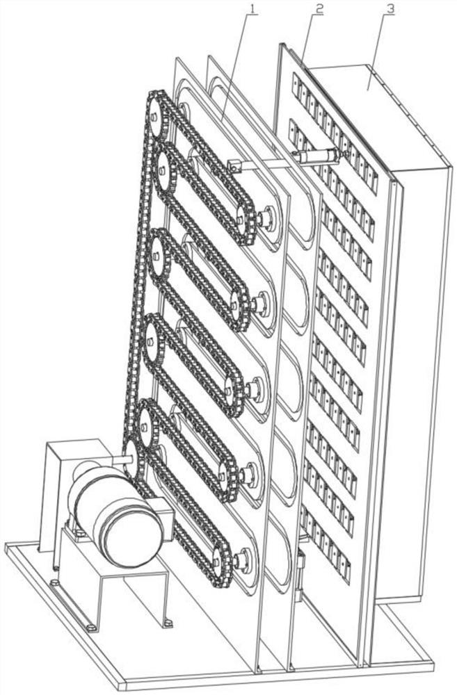
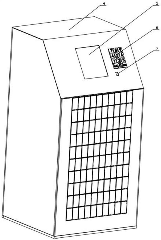
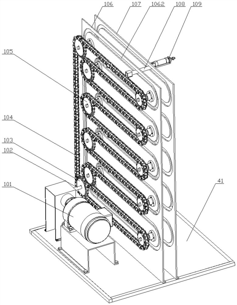
[0053] Such as Figure 1 to Figure 2 As shown, a door opening part 1, a door closing part 2, a key storage part 3, a frame 4, a touch screen 5, a numeric keypad 6 and a fingerprint reader 7 are shown in a cabinet body of a smart key storage cabinet. The door opening part 1 is used to open the key box wicket 304 of the key storage part 3, and deposits the key in the key box for the user, or takes out the key from the key box. The door closing part 2 closes the key box wicket 304, and the key storage part 3 It consists of an array of key boxes for storing keys. The frame 4 is welded by profiles, and the front panel, rear panel, left panel, right panel, upper panel and lower panel are arranged at the front, rear, left, right, upper and lower parts, and the touch screen 5, numeric keypad 6 and fingerprint reader 7 are installed on the front panel , The door opening part 1, the door closing part 2 and the key storage part 3 are all installed in the frame 4. The touch screen 5 dis...

example 2

[0059] The difference between Example 2 and Example 1 is that the transmission assembly of the door opening part 1 in Example 1 adopts a chain transmission mechanism, and the transmission assembly of the door opening part 1 in Example 2 adopts a belt transmission mechanism.

[0060] Such as Figure 16 As shown, the belt transmission mechanism includes a motor 508, a driving pulley shaft 503, a driving pulley 504, a belt 505, a driven pulley 506, a driven pulley shaft 507, a small bevel gear 501 and a large bevel gear 502, the driving belt The wheel shaft 503 is rotatably installed on the rear vertical plate through the bearing with seat, and several of the driven sprocket shafts 507 are fixedly installed on the rear vertical plate through the end flanges. The driving pulley 504 and the large The bevel gears 502 are fixedly installed on the driving pulley shaft 503 respectively through the flat key circumferential direction, the driven pulley 506 is vacantly sleeved on the driv...


PUM


Abstract

The invention discloses an intelligent key storage cabinet body and a working method thereof. The intelligent key storage cabinet body includes a door opening part, a door closing part, a key storage part, a frame, a touch screen, a numeric keypad and a fingerprint identifier. The door opening part is used for Open the small door of the key box of the key storage part, and the door closing part is used to close the small door of the key box. The key storage part is formed by an array of key boxes for storing keys, and the frame is welded by profiles. There are front panel, rear panel, left panel, right panel, upper panel and lower panel arranged at its front, back, left, right, upper and lower parts, touch screen, numeric keypad and fingerprint reader are installed on the front panel, door opening parts, door closing parts and key storage parts are all mounted within the frame described. The body of the intelligent key storage cabinet can be equipped with multiple key boxes, which is convenient for unified storage and management of keys, and has a compact structure, which avoids messy cable layout and too many connectors, which affect the performance of the equipment.

Description

technical field [0001] The invention relates to the technical field of object storage, in particular to an object storage cabinet with a small volume and light weight. Background technique [0002] The key is a special item. If it is stolen or lost due to management negligence, it will cause great security risks and heavy losses. [0003] At present, most units have many keys to manage, and the manual management mode is mainly adopted. However, the method of manual key distribution is relatively backward, and it will waste a lot of human and financial resources. Not only is the efficiency low, but also the number of keys stored is limited. Smart key management for units. In the smart key cabinet industry, the key management and control stations of the existing products adopt an independent control design, and each station is connected by a cable for communication signal transmission. [0004] However, in the existing smart key cabinets, usually due to the large number of ...

Claims


Application Information

Patent Timeline
Patent Type & Authority Patents(China)
IPC IPC(8): A47B81/00A47B97/00E05F15/53E05F1/10
CPCA47B81/00A47B97/00E05B19/0005E05F1/10E05Y2900/20E05F15/53
Inventor 齐继阳张艳琼刘亮罗生华李铁柱
Owner 无锡棱光智慧物联技术有限公司
Learn More