Spiral-flow type sand-removing, sand-discharging and filtering device for agricultural irrigation

An agricultural irrigation and swirling technology, which is applied in the field of swirling sand removal and sand filtration devices, can solve the problems of inconvenient cleaning and achieve the effects of short opening time, low loss and easy cleaning operation

Active Publication Date: 2020-08-18
ANHUI LONGCOM INTERNET OF THINGS
View PDF14 Cites 0 Cited by
  • Summary
  • Abstract
  • Description
  • Claims
  • Application Information

AI Technical Summary

Problems solved by technology

[0006] 3. Through the cooperation of the output pump and the No. 2 water pipe, although the irrigation water flowing from the No. 1 sand filter tube to the conical tube and the partition can be re-transported to the upper tube, but this process will also have some small particles of sand As the irrigation water passes through the No. 1 sand filter cartridge, and then flows together with the water flow, no matter whether the output pump itself has a filter screen or not, this part of the small sand particles has not been well treated. With the filter screen, the small particles The sand particles will eventually remain on the No. 1 water pipe, which is inconvenient to clean. Without a filter, the small particle sand particles will be re-sanded in the cylinder with the water, and the small particle sand particles will not be well cleaned. to remove

Method used


Image

  • Spiral-flow type sand-removing, sand-discharging and filtering device for agricultural irrigation
  • Spiral-flow type sand-removing, sand-discharging and filtering device for agricultural irrigation
  • Spiral-flow type sand-removing, sand-discharging and filtering device for agricultural irrigation

Examples


Embodiment Construction

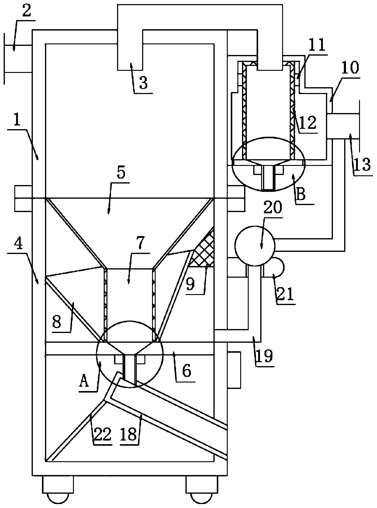
[0024] The following will clearly and completely describe the technical solutions in the embodiments of the present invention with reference to the accompanying drawings in the embodiments of the present invention. Obviously, the described embodiments are only some, not all, embodiments of the present invention. Based on the embodiments of the present invention, all other embodiments obtained by persons of ordinary skill in the art without making creative efforts belong to the protection scope of the present invention.

[0025] In describing the present invention, it should be understood that the terms "upper", "lower", "front", "rear", "left", "right", "top", "bottom", "inner", " The orientation or positional relationship indicated by "outside", etc. is based on the orientation or positional relationship shown in the drawings, and is only for the convenience of describing the present invention and simplifying the description, rather than indicating or implying that the referre...


PUM


Abstract

The invention discloses a spiral-flow type sand-removing, sand-discharging and filtering device for agricultural irrigation. The device comprises a water inlet pipeline and a water outlet pipeline, which are installed on an upper cylinder body; a first conical cylinder, a partition plate and a first sand filtering cylinder, which are fixedly installed in a lower cylinder body; and a second conicalcylinder and a filter screen, which are fixedly installed in the lower cylinder body; wherein the lower end of the second conical cylinder is fixed to the partition plate, the second conical cylinderhas a hollow structure with the two communicated ends, and the first sand filtering barrel is located in the second conical cylinder. The device has the advantages that the whole sand removing and discharging operation is simple and convenient, the use cost of the sand discharging operation is relatively low; irrigation water loss generated in the whole sand removing and discharging process is relatively low, the cleaning operation of small-particle sand leaking out of the first sand filtering cylinder is relatively easy and convenient; and meanwhile, through cooperation of the second conicalcylinder and the filter screen, part of irrigation water does not need to be conveyed into the upper cylinder again to be subjected to sand removing operation again after being filtered, and the irrigation water can be directly conveyed into a drainage pipeline to be used.

Description

technical field [0001] The invention relates to a filter device, in particular to a cyclone type sand removal filter device for agricultural irrigation. Background technique [0002] After searching, the patent authorized invention with the patent number CN106422515B discloses a swirl type sand removal and sand removal filter device for agricultural irrigation, including an upper cylinder and a lower cylinder, and it is characterized in that the upper part of the upper cylinder The front side is fixedly connected with a water inlet pipe, the inside of the upper cylinder is provided with an outlet pipe, the outlet pipe passes through the upper wall of the upper cylinder and the water inlet end of the outlet pipe is located inside the upper cylinder. [0003] But this desanding filter device also has the following deficiencies in the specific use process: [0004] 1. The No. 1 sand filter tube is directly connected with the conical tube and the sand outlet tube, and part of t...

Claims


Application Information

Patent Timeline
Patent Type & Authority Applications(China)
IPC IPC(8): B01D36/04
CPCB01D36/045
Inventor 汪文羽
Owner ANHUI LONGCOM INTERNET OF THINGS
Why Eureka
Try Eureka