Supercharge Your Innovation With Domain-Expert AI Agents!

Forming device and forming machining method of reinforcement cage

A forming device and steel cage technology, applied to wire processing, other household appliances, wire mesh, etc., can solve the problems of low accuracy and achieve the effects of ensuring later construction, simple and practical structure, and improving work efficiency

Pending Publication Date: 2020-08-18
安徽省路港工程有限责任公司
View PDF0 Cites 1 Cited by
  • Summary
  • Abstract
  • Description
  • Claims
  • Application Information

AI Technical Summary

Problems solved by technology

[0004] The purpose of the present invention is to provide a steel cage forming device and its forming processing method, to solve the technical problem that the accuracy of longitudinal staggered positioning and circumferential spacing positioning of adjacent longitudinally stressed steel bar ends of the steel cage is not high at the present stage

Method used


Image

  • Forming device and forming machining method of reinforcement cage
  • Forming device and forming machining method of reinforcement cage
  • Forming device and forming machining method of reinforcement cage

Examples


Embodiment Construction

[0047]In order to make the purpose, technical solutions and advantages of the embodiments of the present invention clearer, the technical solutions in the embodiments of the present invention will be clearly and completely described below in conjunction with the embodiments of the present invention. Obviously, the described embodiments are part of the present invention Examples, not all examples. Based on the embodiments of the present invention, all other embodiments obtained by persons of ordinary skill in the art without creative efforts fall within the protection scope of the present invention.

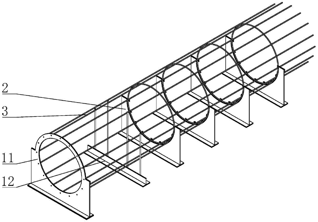
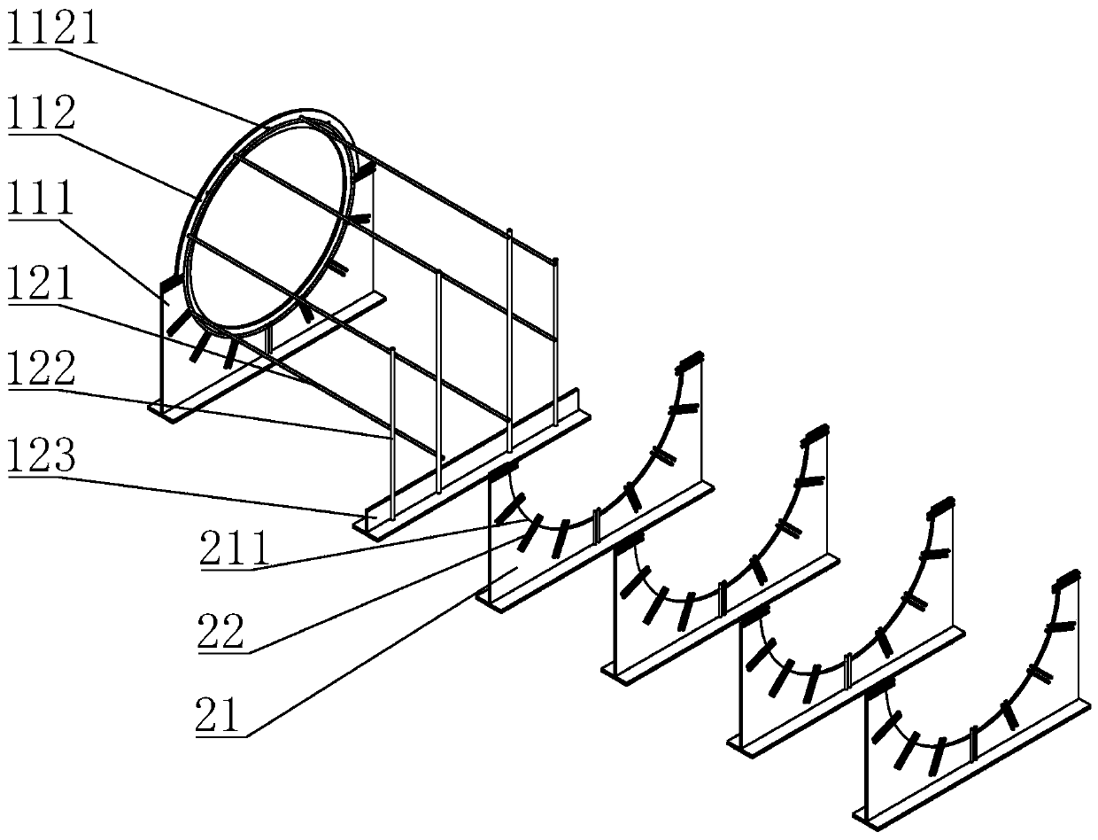
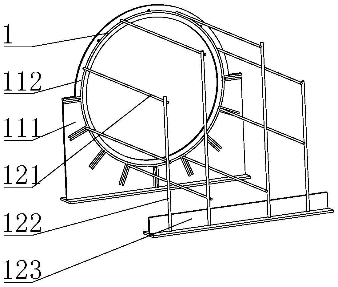
[0048] combined with Figure 1 to Figure 11 , the invention provides a reinforcement cage forming device and a forming processing method thereof, to solve the current technical problem that the accuracy of longitudinal staggered positioning and circumferential spacing positioning of the ends of adjacent longitudinally stressed steel bars of the reinforcement cage is not high.

[...


PUM


Abstract

The invention provides a forming device and forming machining method of a reinforcement cage. A locating plate corresponding to longitudinal protruding load-bearing bars on the reinforcement cage is arranged on an outward protruding steel bar locating frame of an end locating mechanism; longitudinal connecting rods are arranged an inward concaved steel bar locating frame; one ends of the longitudinal connecting rods are connected with the locating plate, and the other ends of the longitudinal connecting rods correspond to longitudinal concaved load-bearing bars on the reinforcement cage; middle locating mechanisms comprise first supports and radial clamp plates; closed stirrups on the reinforcement cage are arranged on limiting clamp grooves of the first supports; and the radial clamp plates are evenly arranged in the radial direction along the outer sides of the limiting clamp grooves. The end locating mechanism and the center locating mechanisms are used for locating the longitudinalprotruding load-bearing bars and the closed stirrups of the reinforcement cage, so that the longitudinal protruding load-bearing bars are evenly distributed on the peripheries of the closed stirrups;meanwhile, the front ends of the longitudinal protruding load-bearing bars are arranged in staggered manner at intervals; and the structure is simple and practical, and work efficiency and the manufacturing quality of the reinforcement cage are greatly improved.

Description

technical field [0001] The invention relates to the technical field of engineering construction auxiliary processing equipment, in particular to a steel cage forming device and a forming processing method thereof. Background technique [0002] Reinforcement cage is an important equipment in building construction. Its function is the same as that of the longitudinal reinforcement of the column. It mainly plays the role of tensile strength. The compressive strength of concrete is high but the tensile strength is very low. The reinforcement cage can restrain the concrete of the pile body, so that it can bear a certain horizontal force and improve the tensile performance. [0003] Existing reinforcement cages are usually connected in sequence by multi-section reinforcement cages to form an integral structure. However, when the longitudinal reinforcement reinforcement of the reinforcement cage body reaches a thickness of 28mm in the existing specified time, it is necessary to use...

Claims


Application Information

Patent Timeline
IPC IPC(8): B21F27/20
CPCB21F27/20
Inventor 李长春陈标张宾郭大锤张硕许雷汪珍珍
Owner 安徽省路港工程有限责任公司
Features
  • R&D
  • Intellectual Property
  • Life Sciences
  • Materials
  • Tech Scout
  • Unparalleled Data Quality
  • Higher Quality Content
  • 60% Fewer Hallucinations
Learn More