Air-injection dedusting device for long-fiber processing spinning equipment

A dust removal device and long-fiber technology, applied in the direction of textiles and papermaking, etc., can solve problems such as inability to remove dust, pollution, and lower economic benefits of work, and achieve the effects of increasing the area of ​​air jet dust removal, improving work efficiency, and improving adequacy

Inactive Publication Date: 2020-08-18
魏传喆
View PDF0 Cites 0 Cited by
  • Summary
  • Abstract
  • Description
  • Claims
  • Application Information

AI Technical Summary

Problems solved by technology

[0003] The influence of external factors on the quality of textile products is also very important, especially in the process of weaving, the dust and impurities in the air will pollute the cotton thread, which will affect the quality of the product in the later stage and reduce the economic benefits of work. The material is discharged from the feed port and then rewound through the winding drum. Usually, the air nozzle is simply installed at the discharge port for air jet dust removal. On the one hand, it cannot fully remove dust and impurities; on the other hand, it cannot perform dust removal according to actual production needs. , reduce dust removal work efficiency, for this reason, the present invention proposes a kind of air jet dust removal device used on long fiber processing and spinning equipment to solve the above problems

Method used


Image

  • Air-injection dedusting device for long-fiber processing spinning equipment
  • Air-injection dedusting device for long-fiber processing spinning equipment
  • Air-injection dedusting device for long-fiber processing spinning equipment

Examples


Embodiment Construction

[0031] The technical solutions in the embodiments of the present invention will be described clearly and completely below. The embodiments of the present invention, and all other embodiments obtained by those of ordinary skill in the art without creative work, fall within the protection scope of the present invention.

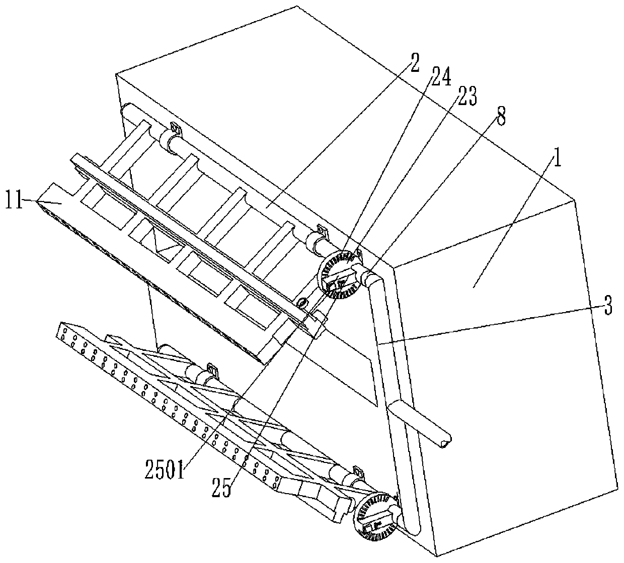
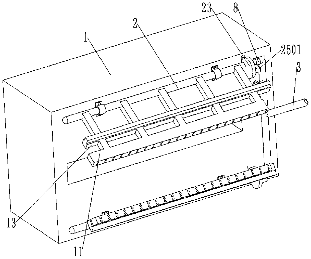
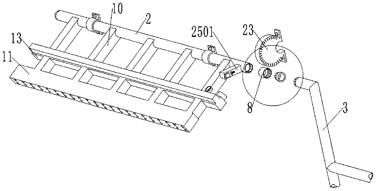
[0032] Please refer to the picture Figure 1 to Figure 7 , The present invention provides a technical solution: an air jet dust removal device used on long fiber processing and spinning equipment, including a discharge port 1, an air branch pipe 2, an air main pipe 3, and an adjusting and fixing structure 25;

[0033] The upper and lower sides of the discharging port 1 are symmetrically provided with air pipes 2 which are fixedly connected with screws on the side of the discharging port 1, and the inner side wall of the air pipe 2 is provided with a connecting groove 4, The inner side of the first connecting groove 4 is provided with a first connecting thread, the ...


PUM


Abstract

The invention discloses an air-injection dedusting device for long-fiber processing spinning equipment. The air-injection dedusting device comprises a discharging outlet, air conveying branch pipes, an air conveying main pipe and an adjusting fixing structure, the air conveying branch pipes are symmetrically arranged on the upper side and the lower side of the discharging outlet, the air conveyingbranch pipes are arranged on the side of the discharging outlet through screws in a fixedly-connected mode, connecting grooves are formed in the inner side walls of one ends of the air conveying branch pipes, first connecting threads are arranged on the inner sides of the first connecting grooves, the connecting grooves are provided with first connecting circular ring convex blocks in a threadedconnection mode, and second connecting threads are arranged on the outer sides of the first connecting circular ring convex blocks. Through an arranged air-injection branch pipe, air-injection box andair-injection adjusting box, the dedusting force intensity of air-injection dedusting can be controlled, the air-injection dedusting area is increased, thus dedusting sufficiency can be improved, andthe working efficiency is improved; and through the arranged adjusting fixing structure, the air-injection angle of the air-injection box can be changed, thus dedusting can be conducted according tothe actual production need, using is convenient and rapid, and the dedusting effect is good.

Description

Technical field [0001] The invention relates to the technical field of spinning equipment, in particular to an air jet dust removal device used on long fiber processing spinning equipment. Background technique [0002] Many plant fibers are twisted together and spun into threads or yarns. These threads or yarns can be used to weave cloth; the earliest spinning machines have a very simple structure and were used in the 14th century; after the 18th century, people invented better spinning Yarn machine, it is this kind of spinning machine that makes the textile industry the largest industry; all spinning machines only do two things: First, they aggregate a large number of short fibers into loose cotton threads, and then pull out the cotton threads a little bit. , Twisted into a dense cotton thread, the cotton thread becomes longer after twisting. Spinning is originally a very ancient activity. Since prehistoric times, humans have learned to spin some shorter fibers into long yarns, ...

Claims


Application Information

Patent Timeline
Patent Type & Authority Applications(China)
IPC IPC(8): D01H11/00
CPCD01H11/005
Inventor 魏传喆
Owner 魏传喆
Why Eureka
Try Eureka